WIPER AND WASHER SYSTEM, Diagnostic DTC:B1245
| DTC Code | DTC Name |
|---|---|
| B1245 | Lost Communication with Wiper ECU LIN |
DESCRIPTION
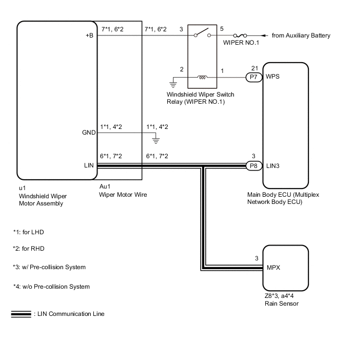
The main body ECU (multiplex network body ECU) and windshield wiper motor assembly communicate via LIN communication. The main body ECU (multiplex network body ECU) stores this DTC if communication becomes abnormal.
| DTC No. | Detection Item | DTC Detection Condition | Trouble Area | Memory | DTC Output from |
|---|---|---|---|---|---|
| B1245 | Lost Communication with Wiper ECU LIN |
DTC Detection Condition:
Malfunction Status:
Malfunction Duration: |
|
○ | Main body ECU (multiplex network body ECU) |
WIRING DIAGRAM
CAUTION / NOTICE / HINT
Note
-
Inspect fuses for circuits related to this system before performing the following inspection procedure.
-
If the main body ECU (multiplex network body ECU) is replaced, refer to Service Bulletin.
PROCEDURE
-
CHECK FOR DTC
-
Clear the DTCs.
Body Electrical > Main Body > Clear DTCs -
Turn the power switch on (IG) and wait for at least 10 seconds.
-
Check for DTCs.
Body Electrical > Main Body > Trouble CodesResult Result Proceed to DTC B1245 is not output. A DTC B1245 is output. B DTC B1245 and B1373 are output. C
A 
USE SIMULATION METHOD TO CHECK Click here
C
GO TO DTC B1373 Click here
B 
-
-
CHECK HARNESS AND CONNECTOR (WIPER MOTOR WIRE - BATTERY)
-
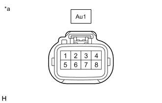
*a Front view of wire harness connector
(to Wiper Motor Wire)
Disconnect the wiper motor wire connector.
-
Measure the voltage according to the value(s) in the table below.
Standard Voltage for LHD Tester Connection Switch Condition Specified Condition Au1-7 - Body ground Approximately 60 seconds have elapsed after power switch is turned off Below 1 V Power switch on (IG) or within approximately 60 seconds of power switch being turned off 11 to 14 V for RHD Tester Connection Switch Condition Specified Condition Au1-6 - Body ground Approximately 60 seconds have elapsed after power switch is turned off Below 1 V Power switch on (IG) or within approximately 60 seconds of power switch being turned off 11 to 14 V Result Proceed to OK NG
NG 
INSPECT WINDSHIELD WIPER SWITCH RELAY (WIPER NO.1) Click here
OK
-
-
INSPECT WIPER MOTOR WIRE
-
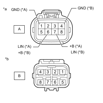
*A for LHD *B for RHD *a Windshield Wiper Motor Assembly Side *b Wire Harness Side Remove the wiper motor wire.
-
Measure the resistance according to the value(s) in the table below.
Standard Resistance for LHD Tester Connection Condition Specified Condition A-1 (GND) - B-1 Always Below 1 Ω A-7 (+B) - B-7 Always Below 1 Ω A-6 (LIN) - B-6 Always Below 1 Ω for RHD Tester Connection Condition Specified Condition A-4 (GND) - B-4 Always Below 1 Ω A-6 (+B) - B-6 Always Below 1 Ω A-7 (LIN) - B-7 Always Below 1 Ω Result Proceed to OK NG
NG
REPLACE WIPER MOTOR WIRE Click here
OK
-
-
CHECK HARNESS AND CONNECTOR (WIPER MOTOR WIRE - BODY GROUND)
-
*a Front view of wire harness connector
(to Wiper Motor Wire)
Disconnect the wiper motor wire connector.
-
Measure the resistance according to the value(s) in the table below.
Standard Resistance for LHD Tester Connection Condition Specified Condition Au1-1 - Body ground Always Below 1 Ω for RHD Tester Connection Condition Specified Condition Au1-4 - Body ground Always Below 1 Ω Result Proceed to OK NG
NG
REPAIR OR REPLACE HARNESS OR CONNECTOR
OK
-
-
CHECK HARNESS AND CONNECTOR (MAIN BODY ECU [MULTIPLEX NETWORK BODY ECU] - WIPER MOTOR WIRE)
-
Disconnect the P8 main body ECU (multiplex network body ECU) connector.
-
Disconnect the Au1 wiper motor wire connector.
-
Measure the resistance according to the value(s) in the table below.
Standard Resistance for LHD Tester Connection Condition Specified Condition P8-3 (LIN3) - Au1-6 (LIN) Always Below 1 Ω for RHD Tester Connection Condition Specified Condition P8-3 (LIN3) - Au1-7 (LIN) Always Below 1 Ω Result Proceed to OK NG
OK
REPLACE WINDSHIELD WIPER MOTOR ASSEMBLY Click here
NG
REPAIR OR REPLACE HARNESS OR CONNECTOR
-
-
INSPECT WINDSHIELD WIPER SWITCH RELAY (WIPER NO.1)
-
Remove the windshield wiper switch relay (WIPER NO.1) form engine room relay block.
-
Inspect the windshield wiper switch relay (WIPER NO.1).
Result Proceed to OK NG
NG
REPLACE WINDSHIELD WIPER SWITCH RELAY (WIPER NO. 1)
OK
-
-
CHECK HARNESS AND CONNECTOR (WINDSHIELD WIPER SWITCH RELAY [WIPER NO.1] - BATTERY AND BODY GROUND)
-
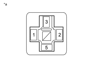
*a Front view of wire harness connector
(to Windshield Wiper Switch Relay [WIPER NO.1])
Remove the windshield wiper switch relay (WIPER NO.1) form engine room relay block.
-
Measure the resistance according to the value(s) in the table below.
Standard Resistance Tester Connection Condition Specified Condition Windshield wiper switch relay (WIPER NO.1) terminal 2 - Body ground Always Below 1 Ω -
Measure the voltage according to the value(s) in the table below.
Standard Voltage Tester Connection Switch Condition Specified Condition Windshield wiper switch relay (WIPER NO.1) terminal 5 - Body ground Power switch off 11 to 14 V Result Proceed to OK NG
NG
REPAIR OR REPLACE HARNESS OR CONNECTOR
OK
-
-
CHECK HARNESS AND CONNECTOR (WINDSHIELD WIPER SWITCH RELAY [WIPER NO.1] - MAIN BODY ECU [MULTIPLEX NETWORK BODY ECU] AND WIPER MOTOR WIRE)
-
Remove the windshield wiper switch relay (WIPER NO.1) form engine room relay block.
-
Disconnect the P7 main body ECU (multiplex network body ECU) connector.
-
Disconnect the Au1 wiper motor wire connector.
-
Measure the resistance according to the value(s) in the table below.
Standard Resistance for LHD Tester Connection Condition Specified Condition P7-21 (WPS) - Windshield wiper switch relay (WIPER NO.1) terminal 1 Always Below 1 Ω Windshield wiper switch relay (WIPER NO.1) terminal 3 - Au1-7 Always Below 1 Ω P7-21 (WPS) or Windshield wiper switch relay (WIPER NO.1) terminal 1 - Body ground Always 10 kΩ or higher Windshield wiper switch relay (WIPER NO.1) terminal 3 or Au1-7 - Body ground Always 10 kΩ or higher for RHD Tester Connection Condition Specified Condition P7-21 (WPS) - Windshield wiper switch relay (WIPER NO.1) terminal 1 Always Below 1 Ω Windshield wiper switch relay (WIPER NO.1) terminal 3 - Au1-6 Always Below 1 Ω P7-21 (WPS) or Windshield wiper switch relay (WIPER NO.1) terminal 1 - Body ground Always 10 kΩ or higher Windshield wiper switch relay (WIPER NO.1) terminal 3 or Au1-6 - Body ground Always 10 kΩ or higher Result Proceed to OK NG
OK
REPLACE MAIN BODY ECU (MULTIPLEX NETWORK BODY ECU) Click here
NG
REPAIR OR REPLACE HARNESS OR CONNECTOR
-