WIPER AND WASHER SYSTEM, Diagnostic DTC:B1375
| DTC Code | DTC Name |
|---|---|
| B1375 | Lost Communication with Wiper Sub Motor Assembly |
DESCRIPTION
| DTC No. | Detection Item | DTC Detection Condition | Trouble Area | Memory | DTC Output from |
|---|---|---|---|---|---|
| B1375 | Lost Communication with Wiper Sub Motor Assembly |
DTC Detection Condition:
Malfunction Condition:
Malfunction Duration: |
|
○ | Windshield wiper motor assembly |
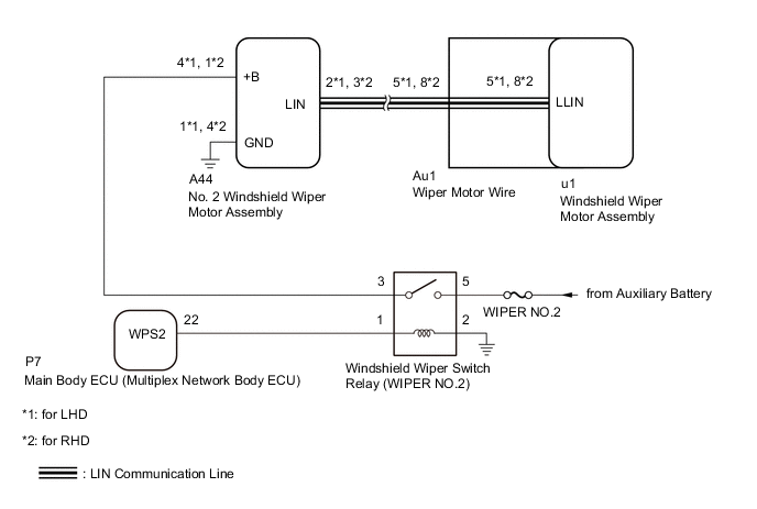
WIRING DIAGRAM
CAUTION / NOTICE / HINT
Note
-
Inspect fuses for circuits related to this system before performing the following inspection procedure.
-
If the main body ECU (multiplex network body ECU) is replaced, refer to Service Bulletin.
PROCEDURE
-
CHECK FOR DTC
-
Clear the DTCs.
Body Electrical > Wiper > Clear DTCs -
Turn the power switch on (IG) and wait for at least 10 seconds.
-
Check for DTCs.
Body Electrical > Wiper > Trouble CodesOK DTC B1375 is not output Result Proceed to OK NG
OK 
USE SIMULATION METHOD TO CHECK Click here
NG 
-
-
CHECK HARNESS AND CONNECTOR (NO. 2 WINDSHIELD WIPER MOTOR ASSEMBLY - BATTERY)
-
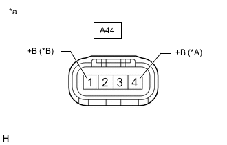
*A for LHD *B for RHD *a Front view of wire harness connector
(to No. 2 Windshield Wiper Motor Assembly)
Disconnect the No. 2 windshield wiper motor assembly connector.
-
Measure the voltage according to the value(s) in the table below.
Standard Voltage for LHD Tester Connection Switch Condition Specified Condition A44-4 (+B) - Body ground Power switch on (IG) or within approximately 60 seconds of power switch being turned off 11 to 14 V Approximately 60 seconds have elapsed after power switch is turned off Below 1 V for RHD Tester Connection Switch Condition Specified Condition A44-1 (+B) - Body ground Power switch on (IG) or within approximately 60 seconds of power switch being turned off 11 to 14 V Approximately 60 seconds have elapsed after power switch is turned off Below 1 V Result Proceed to OK NG
NG 
INSPECT WINDSHIELD WIPER SWITCH RELAY (WIPER NO.2) Click here
OK
-
-
CHECK HARNESS AND CONNECTOR (NO. 2 WINDSHIELD WIPER MOTOR ASSEMBLY - BODY GROUND)
-
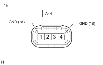
*A for LHD *B for RHD *a Front view of wire harness connector
(to No. 2 Windshield Wiper Motor Assembly)
Disconnect the No. 2 windshield wiper motor assembly connector.
-
Measure the resistance according to the value(s) in the table below.
Standard Resistance for LHD Tester Connection Condition Specified Condition A44-1 (GND) - Body ground Always Below 1 Ω for RHD Tester Connection Condition Specified Condition A44-4 (GND) - Body ground Always Below 1 Ω Result Proceed to OK NG
NG
REPAIR OR REPLACE HARNESS OR CONNECTOR
OK
-
-
CHECK NO. 2 WINDSHIELD WIPER MOTOR ASSEMBLY
-
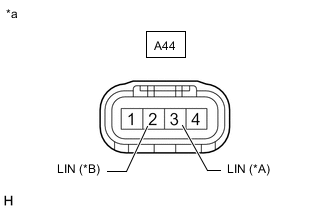
*A for LHD *B for RHD *a Front view of wire harness connector
(to No. 2 Windshield Wiper Motor Assembly)
Disconnect the No. 2 windshield wiper motor assembly connector.
-
Connect an oscilloscope to the rain sensor connector.
-
Check for pulses.
OK for LHD Tester Connection Switch Condition Specified Condition A44-2 (LIN) - Body ground Power switch on (IG) Pulse generation for RHD Tester Connection Switch Condition Specified Condition A44-3 (LIN) - Body ground Power switch on (IG) Pulse generation Result Proceed to OK NG
NG
REPLACE NO. 2 WINDSHIELD WIPER MOTOR ASSEMBLY Click here
OK
-
-
INSPECT WIPER MOTOR WIRE
-
Remove the wiper motor wire.
-
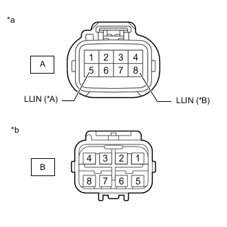
*A for LHD *B for RHD *a Windshield Wiper Motor Assembly Side *b Wire Harness Side Measure the resistance according to the value(s) in the table below.
Standard Resistance for LHD Tester Connection Condition Specified Condition A-5 (LLIN) - B-5 Always Below 1 Ω for RHD Tester Connection Condition Specified Condition A-8 (LLIN) - B-8 Always Below 1 Ω Result Proceed to OK NG
NG
REPLACE WIPER MOTOR WIRE Click here
OK
-
-
CHECK HARNESS AND CONNECTOR (NO. 2 WINDSHIELD WIPER MOTOR ASSEMBLY - WIPER MOTOR WIRE)
-
Disconnect the A44 No. 2 windshield wiper motor assembly connector.
-
Disconnect the Au1 wiper motor wire connector.
-
Measure the resistance according to the value(s) in the table below.
Standard Resistance for LHD Tester Connection Condition Specified Condition A44-2 (LIN) - Au1-5 Always Below 1 Ω A44-2 (LIN) or Au1-5 - Body ground Always 10 kΩ or higher for RHD Tester Connection Condition Specified Condition A44-3 (LIN) - Au1-8 Always Below 1 Ω A44-3 (LIN) or Au1-8 - Body ground Always 10 kΩ or higher Result Proceed to OK NG
OK
REPLACE NO. 2 WINDSHIELD WIPER MOTOR ASSEMBLY Click here
NG
REPAIR OR REPLACE HARNESS OR CONNECTOR
-
-
INSPECT WINDSHIELD WIPER SWITCH RELAY (WIPER NO.2)
-
Remove the windshield wiper switch relay (WIPER NO.2) form engine room relay block.
-
Inspect the windshield wiper switch relay (WIPER NO.2).
Result Proceed to OK NG
NG
REPLACE WINDSHIELD WIPER SWITCH RELAY (WIPER NO.2)
OK
-
-
CHECK HARNESS AND CONNECTOR (WINDSHIELD WIPER SWITCH RELAY [WIPER NO.2] - BATTERY AND BODY GROUND)
-
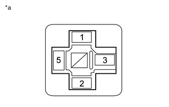
*a Front view of wire harness connector
(to Windshield Wiper Switch Relay [WIPER NO.2])
Remove the windshield wiper switch relay (WIPER NO.2) form engine room relay block.
-
Measure the resistance according to the value(s) in the table below.
Standard Resistance Tester Connection Condition Specified Condition Windshield wiper switch relay (WIPER NO.2) terminal 2 - Body ground Always Below 1 Ω -
Measure the voltage according to the value(s) in the table below.
Standard Voltage Tester Connection Switch Condition Specified Condition Windshield wiper switch relay (WIPER NO.2) terminal 5 - Body ground Power switch off 11 to 14 V Result Proceed to OK NG
NG
REPAIR OR REPLACE HARNESS OR CONNECTOR
OK
-
-
CHECK HARNESS AND CONNECTOR (WINDSHIELD WIPER SWITCH RELAY [WIPER NO.2] - MAIN BODY ECU [MULTIPLEX NETWORK BODY ECU] AND NO. 2 WINDSHIELD WIPER MOTOR ASSEMBLY)
-
Remove the windshield wiper switch relay (WIPER NO.2) form engine room relay block.
-
Disconnect the P7 main body ECU (multiplex network body ECU) connector.
-
Disconnect the A44 No. 2 windshield wiper motor assembly connector.
-
Measure the resistance according to the value(s) in the table below.
Standard Resistance for LHD Tester Connection Condition Specified Condition P7-22 (WPS2) - windshield wiper switch relay (WIPER NO.2) terminal 1 Always Below 1 Ω Windshield wiper switch relay (WIPER NO.2) terminal 3 - A44-4 (+B) Always Below 1 Ω P7-22 (WPS2) or windshield wiper switch relay (WIPER NO.2) terminal 1 - Body ground Always 10 kΩ or higher Windshield wiper switch relay (WIPER NO.2) terminal 3 or A44-4 (+B) - Body ground Always 10 kΩ or higher for RHD Tester Connection Condition Specified Condition P7-22 (WPS2) - windshield wiper switch relay (WIPER NO.2) terminal 1 Always Below 1 Ω Windshield wiper switch relay (WIPER NO.2) terminal 3 - A44-1 (+B) Always Below 1 Ω P7-22 (WPS2) or windshield wiper switch relay (WIPER NO.2) terminal 1 - Body ground Always 10 kΩ or higher Windshield wiper switch relay (WIPER NO.2) terminal 3 or A44-1 (+B) - Body ground Always 10 kΩ or higher Result Proceed to OK NG
OK
REPLACE MAIN BODY ECU (MULTIPLEX NETWORK BODY ECU) Click here
NG
REPAIR OR REPLACE HARNESS OR CONNECTOR
-