LUGGAGE COMPARTMENT DOOR OPENER SYSTEM Luggage Compartment Door Opener does not Operate Using Cabin Switch
DESCRIPTION
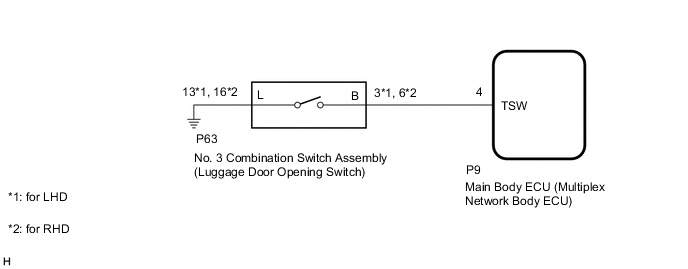
The No. 3 combination switch assembly (luggage door opening switch) signal is sent to the main body ECU (multiplex network body ECU). If the luggage compartment door opener system does not operate with the No. 3 combination switch assembly (luggage door opening switch) operation, there may be a malfunction in the circuit of the No. 3 combination switch assembly (luggage door opening switch).
WIRING DIAGRAM
CAUTION / NOTICE / HINT
Note
If the main body ECU (multiplex network body ECU) is replaced, refer to Service Bulletin.
PROCEDURE
-
READ VALUE USING GTS
-
Read the Data List according to the display on the GTS.
Body Electrical > Main Body > Data ListTester Display Measurement Item Range Normal Condition Diagnostic Note Trunk/BDoor Open SW No. 3 combination switch assembly (luggage door opening switch) signal OFF or ON OFF: No. 3 combination switch assembly (luggage door opening switch) off
ON: No. 3 combination switch assembly (luggage door opening switch) on
-
Body Electrical > Main Body > Data ListTester Display Trunk/BDoor Open SW OK The No. 3 combination switch assembly (luggage door opening switch) functions as specified in the normal condition column. Result Proceed to OK NG
OK 
REPLACE MAIN BODY ECU (MULTIPLEX NETWORK BODY ECU) Click here
NG 
-
-
INSPECT NO. 3 COMBINATION SWITCH ASSEMBLY (LUGGAGE DOOR OPENING SWITCH)
-
Remove the No. 3 combination switch assembly (luggage door opening switch).
-
Inspect the No. 3 combination switch assembly (luggage door opening switch).
Result Proceed to OK NG
NG
REPLACE NO. 3 COMBINATION SWITCH ASSEMBLY (LUGGAGE DOOR OPENING SWITCH) Click here
OK
-
-
CHECK HARNESS AND CONNECTOR (NO. 3 COMBINATION SWITCH ASSEMBLY [LUGGAGE DOOR OPENING SWITCH] - MAIN BODY ECU [MULTIPLEX NETWORK BODY ECU] AND BODY GROUND)
-
Disconnect the P63 No. 3 combination switch assembly (luggage door opening switch) connector.
-
Disconnect the P9 main body ECU (multiplex network body ECU) connector.
-
Measure the resistance according to the value(s) in the table below.
Standard Resistance for LHD Tester Connection Condition Specified Condition P63-3 (B) - P9-4 (TSW) Always Below 1 Ω P63-13 (L) - Body ground Always Below 1 Ω P63-3 (B) or P9-4 (TSW) - Body ground Always 10 kΩ or higher for RHD Tester Connection Condition Specified Condition P63-6 (B) - P9-4 (TSW) Always Below 1 Ω P63-16 (L) - Body ground Always Below 1 Ω P63-6 (B) or P9-4 (TSW) - Body ground Always 10 kΩ or higher Result Proceed to OK NG
OK
REPLACE MAIN BODY ECU (MULTIPLEX NETWORK BODY ECU) Click here
NG
REPAIR OR REPLACE HARNESS OR CONNECTOR
-