LUGGAGE COMPARTMENT DOOR OPENER SYSTEM Luggage Compartment Door Opener does not Operate Using Any Operation
DESCRIPTION
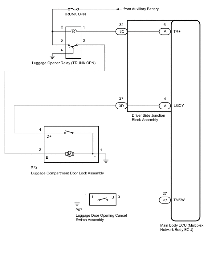
The luggage compartment door opener system controls the main body ECU (multiplex network body ECU) and operates the luggage compartment door lock motor. If the luggage compartment door opener system does not operate using any of the operations, a malfunction related to the luggage compartment door opener system operation conditions or main body ECU (multiplex network body ECU) malfunction are possible causes.
WIRING DIAGRAM
CAUTION / NOTICE / HINT
Note
-
Inspect the fuses for circuits related to this system before performing the following procedure.
-
The luggage compartment door opener system uses the CAN communication system. First, confirm that there is no malfunction in the CAN communication system. Refer to the How to Proceed with Troubleshooting procedure.
-
If the main body ECU (multiplex network body ECU) is replaced, refer to Registration.
PROCEDURE
-
CHECK POWER DOOR LOCK CONTROL SYSTEM
-
Check power door lock control system operation.
OK Power door lock control system is normal. Result Proceed to OK NG
NG 
GO TO POWER DOOR LOCK CONTROL SYSTEM Click here
OK 
-
-
CHECK WIRELESS DOOR LOCK CONTROL SYSTEM
-
Check wireless door lock control system operation.
OK Wireless door lock control system is normal. Result Proceed to OK NG
NG
GO TO WIRELESS DOOR LOCK CONTROL SYSTEM Click here
OK
-
-
PERFORM ACTIVE TEST USING GTS
-
Perform the Active Test according to the display on the GTS.
Body Electrical > Main Body > Active TestTester Display Measurement Item Control Range Diagnostic Note Trunk and Back-Door Open Operate luggage compartment door lock assembly latch release OFF or ON -
Body Electrical > Main Body > Active TestTester Display Trunk and Back-Door Open OK Luggage compartment door lock assembly latch release motor operates normally. Result Proceed to OK NG
NG 
INSPECT LUGGAGE COMPARTMENT DOOR LOCK ASSEMBLY Click here
OK
-
-
READ VALUE USING GTS
-
Read the Data List according to the display on the GTS.
Body Electrical > Main Body > Data ListTester Display Measurement Item Range Normal Condition Diagnostic Note Trunk Main SW Luggage door opening cancel switch assembly signal OFF or ON OFF: Luggage door opening cancel switch assembly off
ON: Luggage door opening cancel switch assembly on
- Luggage Courtesy SW Luggage compartment door courtesy switch signal OFF or ON OFF: Luggage compartment door courtesy switch off
ON: Luggage compartment door courtesy switch on
-
Body Electrical > Main Body > Data ListTester Display Trunk Main SW Luggage Courtesy SW Result Result Proceed to The Data List changes according to each operation A The Data List "Trunk Main SW" does not change according to the luggage door opening cancel switch assembly being operated. B The Data List "Luggage Courtesy SW" does not change according to the luggage compartment door opening or closing. C
A
REPLACE MAIN BODY ECU (MULTIPLEX NETWORK BODY ECU) Click here
B
INSPECT LUGGAGE DOOR OPENING CANCEL SWITCH ASSEMBLY Click here
C
INSPECT LUGGAGE COMPARTMENT DOOR LOCK ASSEMBLY Click here
-
-
INSPECT LUGGAGE COMPARTMENT DOOR LOCK ASSEMBLY
-
Remove the luggage compartment door lock assembly.
-
Inspect the luggage compartment door lock assembly.
Result Proceed to OK NG
NG
REPLACE LUGGAGE COMPARTMENT DOOR LOCK ASSEMBLY Click here
OK
-
-
INSPECT LUGGAGE OPENER RELAY (TRUNK OPN)
-
Remove the luggage opener relay (TRUNK OPN) from the No. 2 luggage room relay block.
-
Inspect the luggage opener relay (TRUNK OPN).
Result Proceed to OK NG
NG
REPLACE LUGGAGE OPENER RELAY (TRUNK OPN)
OK
-
-
CHECK HARNESS AND CONNECTOR (LUGGAGE COMPARTMENT DOOR LOCK ASSEMBLY - LUGGAGE OPENER RELAY [TRUNK OPN] AND BODY GROUND)
-
Disconnect the X72 luggage compartment door lock assembly connector.
-
Remove the luggage opener relay (TRUNK OPN) from the No. 2 luggage room relay block.
-
Measure the resistance according to the value(s) in the table below.
Standard Resistance Tester Connection Condition Specified Condition X72-3 (B) - Luggage opener relay (TRUNK OPN) terminal 3 Always Below 1 Ω X72-1 (E) - Body ground Always Below 1 Ω X72-3 (B) or Luggage opener relay (TRUNK OPN) terminal 3 - Body ground Always 10 kΩ or higher Result Proceed to OK NG
NG
REPAIR OR REPLACE HARNESS OR CONNECTOR
OK
-
-
CHECK HARNESS AND CONNECTOR (LUGGAGE OPENER RELAY [TRUNK OPN] - BATTERY AND BODY GROUND)
-
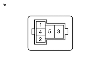
*a Front view of wire harness connector
(to Luggage Opener Relay [TRUNK OPN])
Remove the luggage opener relay (TRUNK OPN) from the No. 2 luggage room relay block.
-
Measure the resistance according to the value(s) in the table below.
Standard Resistance Tester Connection Condition Specified Condition Luggage opener relay (TRUNK OPN) terminal 4 - Body ground Always Below 1 Ω -
Measure the voltage according to the value(s) in the table below.
Standard Voltage Tester Connection Switch Condition Specified Condition Luggage opener relay (TRUNK OPN) terminal 2 - Body ground Power switch off 11 to 14 V Luggage opener relay (TRUNK OPN) terminal 5 - Body ground Power switch off 11 to 14 V Result Proceed to OK NG
NG
REPAIR OR REPLACE HARNESS OR CONNECTOR
OK
-
-
CHECK HARNESS AND CONNECTOR (LUGGAGE OPENER RELAY [TRUNK OPN] - DRIVER SIDE JUNCTION BLOCK ASSEMBLY)
-
Remove the luggage opener relay (TRUNK OPN) from the No. 2 luggage room relay block.
-
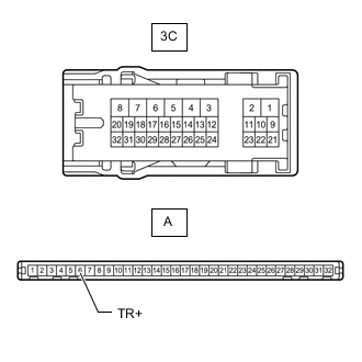
Disconnect the 3C driver side junction block assembly connector.
-
Measure the resistance according to the value(s) in the table below.
Standard Resistance Tester Connection Condition Specified Condition Luggage opener relay (TRUNK OPN) terminal 1 - 3C-32 Always Below 1 Ω Luggage opener relay (TRUNK OPN) terminal 1 or 3C-32 - Body ground Always 10 kΩ or higher Result Proceed to OK NG
NG
REPAIR OR REPLACE HARNESS OR CONNECTOR
OK
-
-
INSPECT DRIVER SIDE JUNCTION BLOCK ASSEMBLY
-
Remove the driver side junction block assembly.
-
Remove the main body ECU (multiplex network body ECU) from driver side junction block assembly.
-
Measure the resistance according to the value(s) in the table below.
Standard Resistance Tester Connection Condition Specified Condition 3C-32 - A-6(TR+) Always Below 1 Ω Result Proceed to OK NG
OK
REPLACE MAIN BODY ECU (MULTIPLEX NETWORK BODY ECU) Click here
NG
REPLACE DRIVER SIDE JUNCTION BLOCK ASSEMBLY Click here
-
-
INSPECT LUGGAGE DOOR OPENING CANCEL SWITCH ASSEMBLY
-
Remove the luggage door opening cancel switch assembly.
-
Inspect the luggage door opening cancel switch assembly.
Result Proceed to OK NG
NG
REPLACE LUGGAGE DOOR OPENING CANCEL SWITCH ASSEMBLY Click here
OK
-
-
CHECK HARNESS AND CONNECTOR (LUGGAGE DOOR OPENING CANCEL SWITCH ASSEMBLY - MAIN BODY ECU [MULTIPLEX NETWORK BODY ECU] AND BODY GROUND)
-
Disconnect the P67 luggage door opening cancel switch assembly connector.
-
Disconnect the P7 main body ECU (multiplex network body ECU) connector.
-
Measure the resistance according to the value(s) in the table below.
Standard Resistance Tester Connection Condition Specified Condition P67-2 (B) - P7-27 (TMSW) Always Below 1 Ω P67-1 (L) - Body ground Always Below 1 Ω P67-2 (B) or P7-27 (TMSW) - Body ground Always 10 kΩ or higher Result Proceed to OK NG
OK
REPLACE MAIN BODY ECU (MULTIPLEX NETWORK BODY ECU) Click here
NG
REPAIR OR REPLACE HARNESS OR CONNECTOR
-
-
INSPECT LUGGAGE COMPARTMENT DOOR LOCK ASSEMBLY
-
Remove the luggage compartment door lock assembly.
-
Inspect the luggage compartment door lock assembly.
Result Proceed to OK NG
NG
REPLACE LUGGAGE COMPARTMENT DOOR LOCK ASSEMBLY Click here
OK
-
-
CHECK HARNESS AND CONNECTOR (LUGGAGE COMPARTMENT DOOR LOCK ASSEMBLY - DRIVER SIDE JUNCTION BLOCK ASSEMBLY)
-
Disconnect the X72 luggage compartment door lock assembly connector.
-
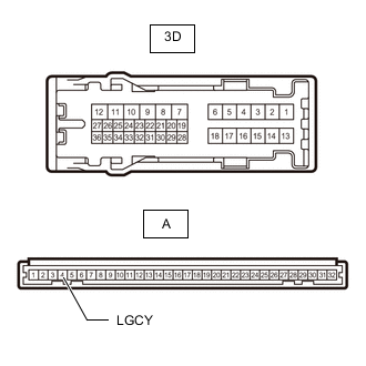
Disconnect the 3D driver side junction block assembly connector.
-
Measure the resistance according to the value(s) in the table below.
Standard Resistance Tester Connection Condition Specified Condition X72-4 (D+) - 3D-27 Always Below 1 Ω X72-4 (D+) or 3D-27 - Body ground Always 10 kΩ or higher Result Proceed to OK NG
NG
REPAIR OR REPLACE HARNESS OR CONNECTOR
OK
-
-
INSPECT DRIVER SIDE JUNCTION BLOCK ASSEMBLY
-
Remove the driver side junction block assembly.
-
Remove the main body ECU (multiplex network body ECU) from the driver side junction block assembly.
-
Measure the resistance according to the value(s) in the table below.
Standard Resistance Tester Connection Condition Specified Condition 3D-27 - A-4 (LGCY) Always Below 1 Ω Result Proceed to OK NG
OK
REPLACE MAIN BODY ECU (MULTIPLEX NETWORK BODY ECU) Click here
NG
REPLACE DRIVER SIDE JUNCTION BLOCK ASSEMBLY Click here
-