WINDSHIELD DEICER SYSTEM Windshield Deicer does not Operate
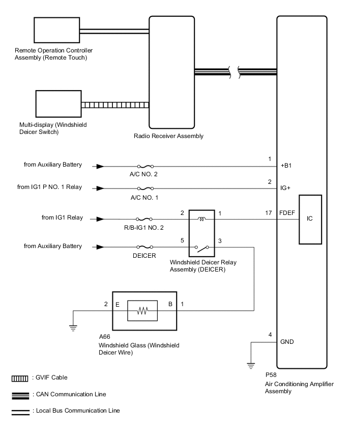
DESCRIPTION
The air conditioning amplifier assembly uses the CAN communication line to send commands to the radio receiver assembly to display the functions controlled by the air conditioning amplifier assembly on the multi-display. When the radio receiver assembly receives these commands, it uses the GVIF cable to display on the multi-display.
When the windshield deicer switch on the air conditioning screen of the multi-display is turned to "ON" with the remote operation controller assembly (remote touch), operation information is sent to the radio receiver assembly using the local bus communication line and the windshield deicer switch operation information is sent from the radio receiver assembly to the air conditioning amplifier assembly via CAN communication. When the air conditioning amplifier assembly receives windshield deicer switch operation information, it turns the windshield deicer relay assembly (DEICER) on and operates the windshield deicer system.
WIRING DIAGRAM
CAUTION / NOTICE / HINT
Note
-
Inspect the fuses for circuits related to this system before performing the following procedure.
-
The windshield deicer system uses the CAN communication system. Inspect the communication function by following How to Proceed with Troubleshooting. Troubleshoot the windshield deicer system after confirming that the communication system is functioning properly.
-
Troubleshoot the windshield deicer system after confirming that the navigation system is functioning properly.
-
Troubleshoot the windshield deicer system after confirming that the air conditioning system is functioning properly.
-
If the auxiliary battery voltage becomes low, windshield deicer operation is canceled to prioritize supplying power to the power steering system.
-
The following malfunctions may occur if a radio receiver assembly from another vehicle is installed to this vehicle. Therefore, when replacing the radio receiver assembly, be sure to replace them with new ones.
-
Communication malfunction DTC is output
-
Does not operate normally
PROCEDURE
-
PERFORM ACTIVE TEST USING GTS (DEICER RELAY (FRONT))
-
Using the GTS, perform the Active Test.
Body Electrical > Air Conditioner > Active TestTester Display Measurement Item Control Range Diagnostic Note Deicer Relay (Front) Windshield glass (windshield deicer wire) OFF or ON -
Body Electrical > Air Conditioner > Active TestTester Display Deicer Relay (Front) OK The windshield deicer system operates normally. Result Proceed to OK NG
NG 
CHECK HARNESS AND CONNECTOR (WINDSHIELD GLASS [WINDSHIELD DEICER WIRE] - BATTERY) Click here
OK 
-
-
CHECK AIR CONDITIONING AMPLIFIER ASSEMBLY
-
Replace the air conditioning amplifier assembly with a new or normally functioning one.
-
Check that the window deicer system operates normally.
OK The window deicer system operates normally. Result Proceed to OK NG
OK 
END (AIR CONDITIONING AMPLIFIER ASSEMBLY IS DEFECTIVE)
NG
REPLACE RADIO RECEIVER ASSEMBLY Click here
-
-
CHECK HARNESS AND CONNECTOR (WINDSHIELD GLASS [WINDSHIELD DEICER WIRE] - BATTERY)
-
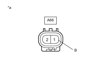
*a Front view of wire harness connector
(to Windshield Glass [Windshield Deicer Wire])
Disconnect the windshield glass (windshield deicer wire) connector.
-
Measure the voltage according to the value(s) in the table below.
Standard Voltage Tester Connection Switch Condition Specified Condition A66-1 (B) - Body ground Power switch on (IG), windshield deicer switch off Below 1 V Power switch on (IG), windshield deicer switch on 11 to 14 V Result Proceed to OK NG
NG
INSPECT WINDSHIELD DEICER RELAY ASSEMBLY (DEICER) Click here
OK
-
-
CHECK HARNESS AND CONNECTOR (WINDSHIELD GLASS [WINDSHIELD DEICER WIRE] - BODY GROUND)
-
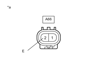
*a Front view of wire harness connector
(to Windshield Glass [Windshield Deicer Wire])
Disconnect the windshield glass (windshield deicer wire) connector.
-
Measure the resistance according to the value(s) in the table below.
Standard Resistance Tester Connection Condition Specified Condition A66-2 (E) - Body ground Always Below 1 Ω Result Proceed to OK NG
OK
REPLACE WINDSHIELD GLASS (WINDSHIELD DEICER WIRE) Click here
NG
REPAIR OR REPLACE HARNESS OR CONNECTOR
-
-
INSPECT WINDSHIELD DEICER RELAY ASSEMBLY (DEICER)
-
Remove the windshield deicer relay assembly (DEICER) from the No. 2 engine room relay block.
-
Inspect the windshield deicer relay assembly (DEICER).
Result Proceed to OK NG
NG
REPLACE WINDSHIELD DEICER RELAY ASSEMBLY (DEICER)
OK
-
-
CHECK HARNESS AND CONNECTOR (WINDSHIELD DEICER RELAY ASSEMBLY [DEICER] - BATTERY)
-
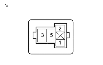
*a Front view of wire harness connector
(to Windshield Deicer Relay Assembly [DEICER])
Remove the windshield deicer relay assembly (DEICER) from the No. 2 engine room relay block.
-
Measure the voltage according to the value(s) in the table below.
Standard Voltage Tester Connection Switch Condition Specified Condition Windshield deicer relay assembly (DEICER) terminal 5 - Body ground Power switch off 11 to 14 V Windshield deicer relay assembly (DEICER) terminal 2 - Body ground Power switch on (IG) 11 to 14 V Result Proceed to OK NG
NG
REPAIR OR REPLACE HARNESS OR CONNECTOR
OK
-
-
CHECK HARNESS AND CONNECTOR (WINDSHIELD DEICER RELAY ASSEMBLY [DEICER] - AIR CONDITIONING AMPLIFIER ASSEMBLY AND WINDSHIELD GLASS [WINDSHIELD DEICER WIRE])
-
Disconnect the A66 windshield glass (windshield deicer wire) connector.
-
Disconnect the P58 air conditioning amplifier assembly connector.
-
Remove the windshield deicer relay assembly (DEICER) from the No. 2 engine room relay block.
-
Measure the resistance according to the value(s) in the table below.
Standard Resistance Tester Connection Condition Specified Condition Windshield deicer relay assembly (DEICER) terminal 3 - A66-1 (B) Always Below 1 Ω Windshield deicer relay assembly (DEICER) terminal 1 - P58-17 (FDEF) Always Below 1 Ω Windshield deicer relay assembly (DEICER) terminal 3 or A66-1 (B) - Body ground Always 10 kΩ or higher Windshield deicer relay assembly (DEICER) terminal 1 or P58-17 (FDEF) - Body ground Always 10 kΩ or higher Result Proceed to OK NG
OK
REPLACE AIR CONDITIONING AMPLIFIER ASSEMBLY Click here
NG
REPAIR OR REPLACE HARNESS OR CONNECTOR
-