INSTRUMENT PANEL SAFETY PAD INSTALLATION
CAUTION / NOTICE / HINT
Tech Tips
-
Use the same procedure for RHD and LHD vehicles.
-
The procedure listed below is for LHD vehicles.
-
A bolt without a torque specification is shown in the standard bolt chart.
PROCEDURE
-
INSTALL INSTRUMENT PANEL SAFETY PAD SUB-ASSEMBLY
-
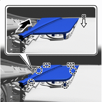
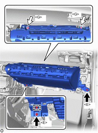
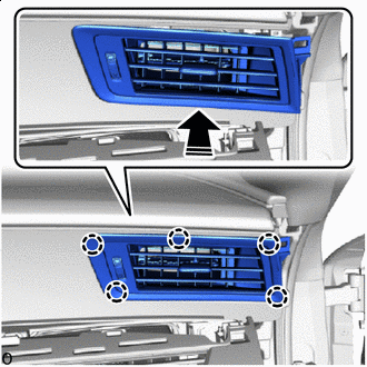
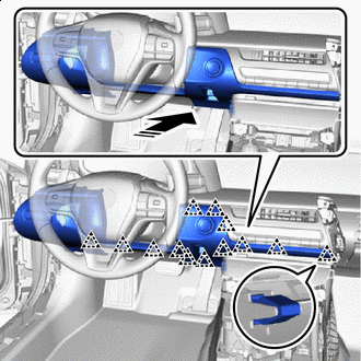
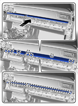
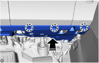
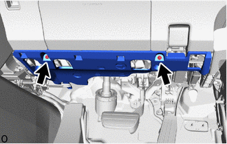
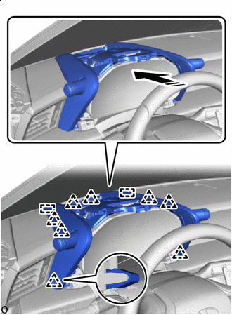
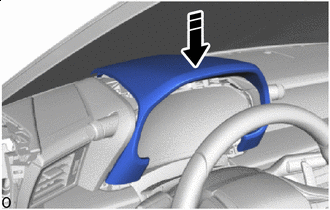
Lift up the instrument panel safety pad sub-assembly and set it on the vehicle as shown in the illustration.
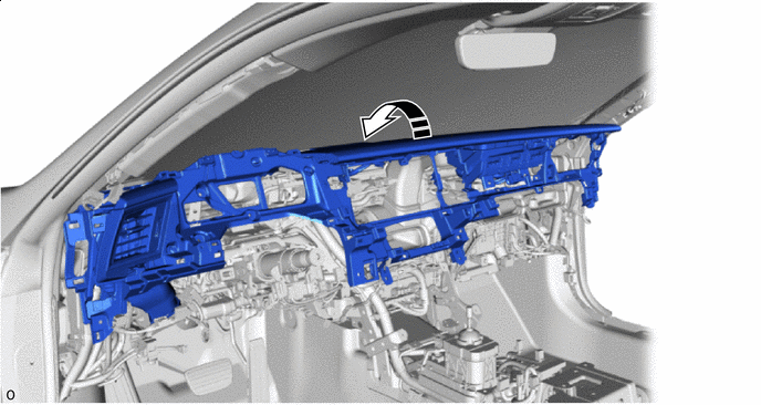

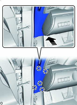
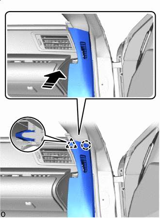
Install in this Direction - - -
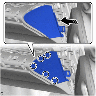
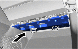
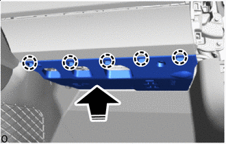
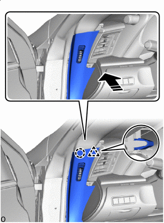
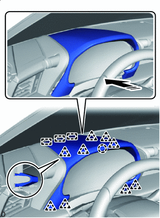
Push as shown in the illustration to insert the guides.
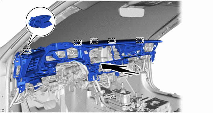
Install in this Direction - - -
for LHD:
-
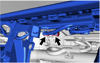
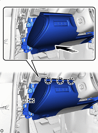
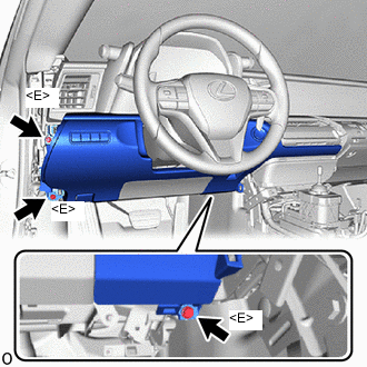
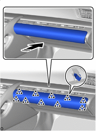
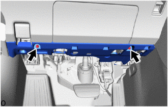
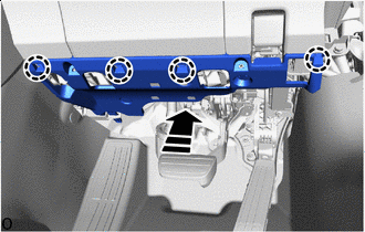
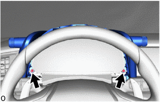
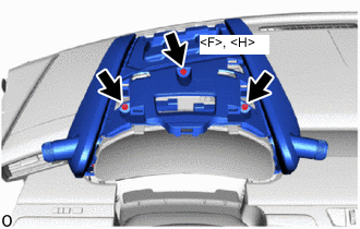
Install the instrument panel safety pad sub-assembly with the 8 bolts <E> and nut <C> or <D>.
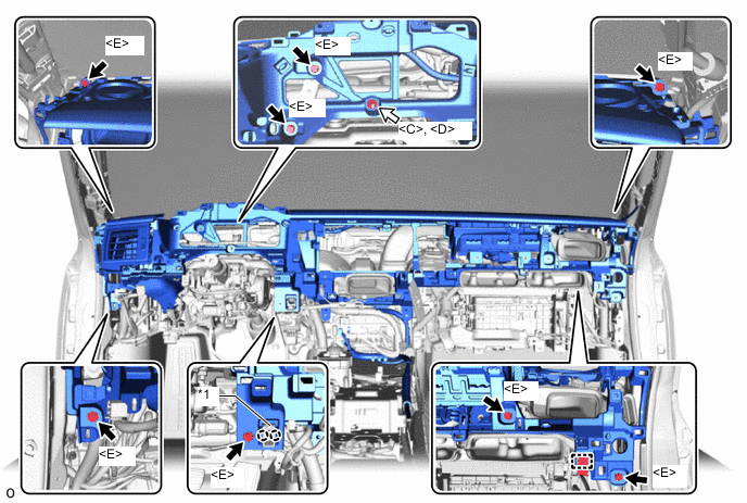
*1 Cooler Thermistor (Recirculated Air Temperature) - - 
Bolt <E> 
Nut <C> or <D> -
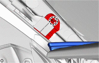
Attach the claw to install the cooler thermistor (recirculated air temperature) to the instrument panel safety pad sub-assembly.
-
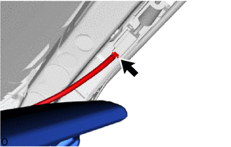
Attach the clamp.
-
-
for RHD:
-
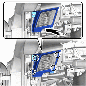
Install the instrument panel safety pad sub-assembly with the 8 bolts <E> and nut <C> or <D>.
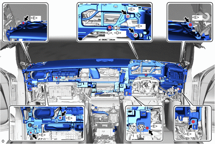
*1 Cooler Thermistor (Recirculated Air Temperature) - - Bolt <E> Nut <C> or <D> -
Attach the claw to install the cooler thermistor (recirculated air temperature) to the instrument panel safety pad sub-assembly.
-
-
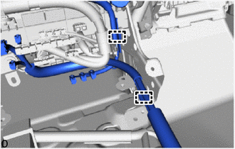
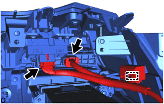
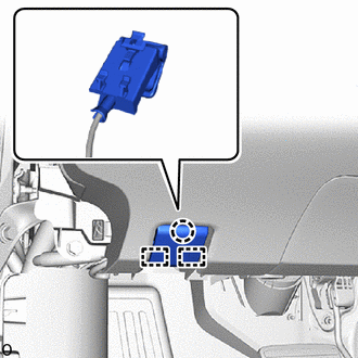
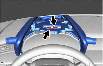
Connect the 2 connectors.
-
for LHD:
-
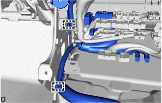
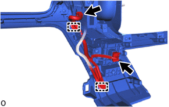
Connect the connector.
-
Attach the clamps.
-
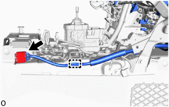
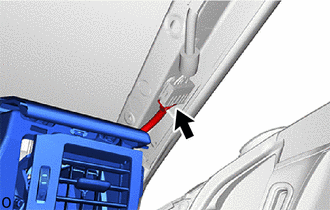
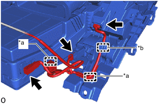
Connect the connector and attach the clamp.
-
-
for RHD:
-
Connect the connector.
-
Attach the clamps.
-
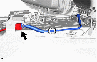
Connect the connector and attach the clamp.
-
-
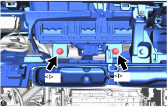
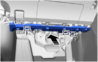
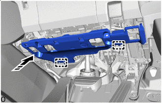
Install the 2 bolts <I>.
- Torque:
- 20 N*m { 204 kgf*cm, 15 ft.*lbf }
-
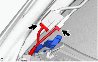
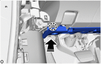
Before connecting the airbag connector, check that the CPA is positioned further back than the housing.
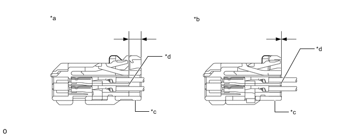
*a CORRECT *b INCORRECT *c CPA *d Housing -
Connect airbag connector:
-
Holding the sides of the CPA, connect it by engaging until a locking sound is heard.
Note
-
When connecting the airbag connector, press and connect it straight so as not to twist it.
-
When connecting the connector, do not hold components other than the CPA.
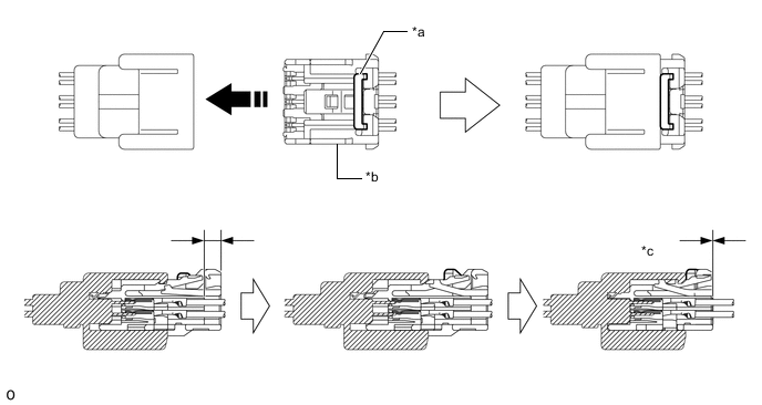
*a Housing Lock *b CPA *c CONNECTED - - Install in this Direction - - -
-
-
-
INSTALL NO. 3 INSTRUMENT PANEL TO COWL BRACE SUB-ASSEMBLY
-
for LHD:
-
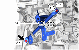
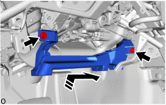
*A w/ Clearance Sonar System Bolt <A> Nut <B> Install the No. 3 instrument panel to cowl brace sub-assembly with the bolt <A> and nut <B>.
- Torque:
- Bolt <A>
- 10 N*m { 102 kgf*cm, 7 ft.*lbf }
- Nut <B>
- 6.0 N*m { 61 kgf*cm, 53 in.*lbf }
-
Attach the clamps.
-
-
for RHD:
-
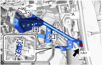
*A w/ Clearance Sonar System *1 DLC3 Bolt <A> Nut <B> Install the No. 3 instrument panel to cowl brace sub-assembly with the bolt <A> and nut <B>.
- Torque:
- Bolt <A>
- 10 N*m { 102 kgf*cm, 7 ft.*lbf }
- Nut <B>
- 6.0 N*m { 61 kgf*cm, 53 in.*lbf }
-
Attach the claws to install the DLC3.
-
Attach the clamps.
-
-
-
INSTALL HEATER TO REGISTER CENTER SUB DUCT
-
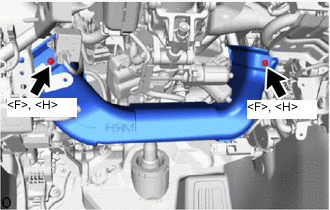
Install the heater to register center sub duct with the 2 screws <F> or <H>.
-
-
INSTALL DOUBLE LOCK DOOR CONTROL RELAY ASSEMBLY (w/ Double Locking System)
-
INSTALL NO. 2 AIR DUCT
-
Install in this Direction Insert the No. 2 air duct in the direction of the arrow shown in the illustration to install it with the 2 bolts.
- Torque:
- 9.8 N*m { 100 kgf*cm, 87 in.*lbf }
-
-
INSTALL STEERING WHEEL SWITCH HOUSING
-
INSTALL LOWER NO. 1 INSTRUMENT PANEL AIRBAG ASSEMBLY
-
INSTALL FRONT NO. 1 SPEAKER ASSEMBLY
-
INSTALL NO. 1 INSTRUMENT PANEL SPEAKER PANEL SUB-ASSEMBLY
-
Install in this Direction (1) 
Install in this Direction (2) Insert the guides in direction indicated by the arrow shown in the illustration.
-
Attach the claws to install the No. 1 instrument panel speaker panel sub-assembly as shown in the illustration.
-
for LHD:
-
Attach the claw to install the connector holder to the vehicle.
-
Connect the 2 connectors.
-
-
-
INSTALL NO. 2 INSTRUMENT PANEL SPEAKER PANEL SUB-ASSEMBLY
-
Install in this Direction (1) Install in this Direction (2) Insert the guides in direction indicated by the arrow shown in the illustration.
-
Attach the claws to install the No. 2 instrument panel speaker panel sub-assembly as shown in the illustration.
-
for RHD:
-
Attach the claw to install the connector holder to the vehicle.
-
Connect the 2 connectors.
-
-
-
INSTALL FRONT PILLAR GARNISH LH
-
INSTALL FRONT PILLAR GARNISH RH
Tech Tips
Use the same procedure described for the LH side.
-
INSTALL MULTI-DISPLAY
-
INSTALL GLOVE COMPARTMENT DOOR ASSEMBLY
-
*a Clamp *b Hook Attach the clamps and pull the hook.
-
Connect the 3 connectors.
-
Install in this Direction Attach the claws in the direction of the arrow shown in the illustration.
-
Bolt <E> Screw <G> Install the glove compartment door assembly with the 2 bolts <E> and 2 screws <G>.
-
Attach the clamp.
-
-
INSTALL LOWER NO. 2 INSTRUMENT PANEL AIRBAG ASSEMBLY
-
INSTALL NO. 2 GLOVE COMPARTMENT PANEL
-
w/ Airbag Cut Off Switch:
Connect the connector.
-
Install in this Direction Attach the claws in the direction of the arrow shown in the illustration to install the No. 2 glove compartment panel.
-
-
INSTALL NO. 2 INSTRUMENT PANEL UNDER COVER SUB-ASSEMBLY
-
Install in this Direction Insert the guides in direction indicated by the arrow shown in the illustration.
-
Connect the connector.
-
Install in this Direction Lift up the No. 2 instrument panel under cover sub-assembly in the direction of the arrow shown in the illustration and attach the claws to install it.
-
-
INSTALL NO. 2 INSTRUMENT PANEL REGISTER ASSEMBLY
-
Remove the protective tape.
-
Connect the connector.
-
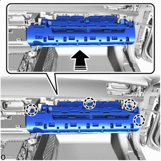
Install in this Direction Attach the claws as shown in the direction of the arrow shown in the illustration to install the No. 2 instrument panel register assembly.
-
-
INSTALL TELEPHONE TRANSCEIVER ASSEMBLY WITH BRACKET (w/ Telematics Transceiver)
-
INSTALL RADIO RECEIVER ASSEMBLY WITH BRACKET
-
INSTALL INTEGRATION CONTROL AND PANEL ASSEMBLY
-
INSTALL INSTRUMENT PANEL REGISTER BEZEL
-
Install in this Direction Attach the claws as shown in the direction of the arrow shown in the illustration to install the instrument panel register bezel.
-
-
INSTALL NO. 1 INSTRUMENT PANEL SAFETY PAD SUB-ASSEMBLY
-
Attach the clamps and connect the 2 connectors.
-
Attach the clamp and connect the 2 connectors.
-
Install in this Direction Attach the clips in the direction of the arrow shown in the illustration.
-
Install in this Direction Attach the claws and align the guides as shown in the direction of the arrow shown in the illustration to install the No. 1 instrument panel safety pad sub-assembly.
-
Install the 3 bolts <E>.
-
-
INSTALL HOOD LOCK CONTROL LEVER SUB-ASSEMBLY
-
Align the guides and attach the claw, connect the hood lock control lever sub-assembly to the No. 1 instrument panel safety pad sub-assembly.
-
-
INSTALL NO. 2 INSTRUMENT PANEL GARNISH SUB-ASSEMBLY
-
Remove the protective tape.
-
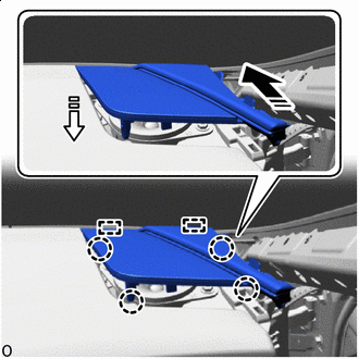
Install in this Direction Attach the claws and guides as shown in the direction of the arrow shown in the illustration to install the No. 2 instrument panel garnish sub-assembly.
-
-
INSTALL CONSOLE BOX ASSEMBLY (for LHD)
-
INSTALL TRANSMISSION FLOOR SHIFT ASSEMBLY (for RHD)
-
INSTALL NO. 1 GLOVE COMPARTMENT PANEL
-
Install in this Direction Attach the clips in the direction of the arrow shown in the illustration to install the No. 1 glove compartment panel.
-
-
INSTALL NO. 1 INSTRUMENT PANEL UNDER COVER SUB-ASSEMBLY
-
for LHD:
-
Install in this Direction Insert the guides in direction indicated by the arrow shown in the illustration.
-
Connect the connector.
-
Install in this Direction Attach the claw in the direction of the arrow shown in the illustration.
-
Install in this Direction Attach the claws in the direction of the arrow shown in the illustration to install the No. 1 instrument panel under cover sub-assembly.
-
Install the 2 screws.
-
-
for RHD:
-
Install in this Direction Insert the guides in direction indicated by the arrow shown in the illustration.
-
Connect the connector.
-
Install in this Direction Attach the claws in the direction of the arrow shown in the illustration to install the No. 1 instrument panel under cover sub-assembly.
-
Install the 2 screws.
-
-
-
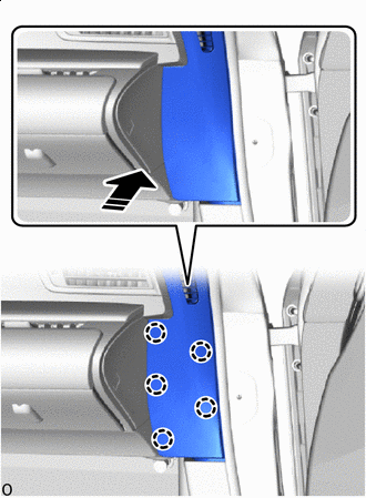
INSTALL FRONT DOOR NO. 2 OPENING TRIM COVER LH
-
Install in this Direction Attach the claw and clip in the installation direction shown in the illustration.
-
Install in this Direction Attach the claws in the direction of the arrow shown in the illustration to install the front door No. 2 opening trim cover LH.
-
-
INSTALL FRONT DOOR NO. 2 OPENING TRIM COVER RH
-
Install in this Direction Attach the claw and clip in the installation direction shown in the illustration.
-
Install in this Direction Attach the claws in the direction of the arrow shown in the illustration to install the front door No. 2 opening trim cover RH.
-
-
INSTALL FRONT DOOR OPENING TRIM COVER LH
-
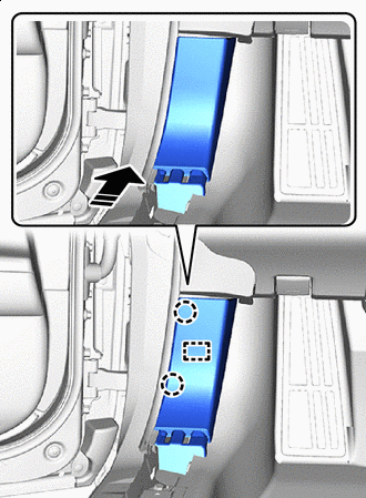
Install in this Direction Attach the claws and insert the guide in the direction of the arrow shown in the illustration to install the front door opening trim cover LH.
-
-
INSTALL FRONT DOOR OPENING TRIM COVER RH
Tech Tips
Use the same procedure described for the LH side.
-
INSTALL FRONT DOOR SCUFF PLATE LH
-
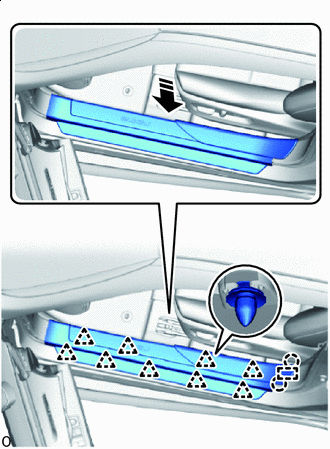
Install in this Direction Attach the claws and align the guide in the direction of the arrow shown in the illustration.
-
Attach the clips.
-
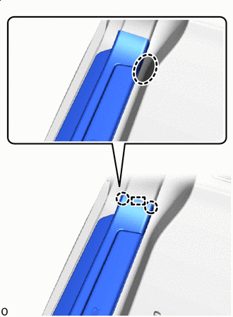

Place hand here Attach the claw on the vehicle exterior side and align the guide.
-
Place your hand at the position shown in the illustration and while pulling towards the center of the vehicle, attach the claw to install the front door scuff plate LH.
-
-
INSTALL FRONT DOOR SCUFF PLATE RH
Tech Tips
Use the same procedure described for the LH side.
-
INSTALL COMBINATION METER ASSEMBLY
-
INSTALL METER HOOD SUB-ASSEMBLY
-
Install in this Direction Insert the guides and attach the clips in the direction of the arrow shown in the illustration to install the meter hood sub-assembly.
-
Install the 2 screws.
-
Install the screw <F> or <H> and 2 screws.
-
Connect the 2 connectors.
-
-
INSTALL CENTER UPPER INSTRUMENT CLUSTER FINISH PANEL
-
Install in this Direction Set the instrument panel center cluster finish panel in the direction of the arrow shown in the illustration.
-
Install in this Direction Insert the guides and attach the claws and clips in the direction of the arrow shown in the illustration to install the upper center instrument cluster finish panel.
-
-
CONNECT CABLE TO NEGATIVE AUXILIARY BATTERY TERMINAL
Note
When disconnecting the cable, some systems need to be initialized after the cable is reconnected.
-
INSTALL NO. 2 DECK BOARD
-
INSPECT AUTOMATIC LIGHT CONTROL SYSTEM
-
CHECK SRS WARNING LIGHT
-
CUSTOMIZE POWER TILT AND POWER TELESCOPIC STEERING COLUMN SYSTEM
-
CHECK STEERING WHEEL CENTER POINT
-
ADJUST PARKING ASSIST MONITOR SYSTEM