INSTRUMENT PANEL SAFETY PAD REMOVAL
CAUTION / NOTICE / HINT
The necessary procedures (adjustment, calibration, initialization or registration) that must be performed after parts are removed, installed or replaced during the instrument panel safety pad sub-assembly removal/installation are shown below.
| Replacement Part or Procedure | Necessary Procedures | Effects / Inoperative when not Performed | Link |
|---|---|---|---|
| Disconnect cable from negative auxiliary battery terminal | Memorize steering angle neutral point | LKA/LDA system | |
| Pre-collision system | |||
| Parking assist monitor system | |||
| Steering sensor zero point calibration | Variable gear ratio steering system |
CAUTION:
Some of these service operations affect the SRS airbag system. Read the precautionary notices concerning the SRS airbag system before servicing.
Tech Tips
-
Use the same procedure as for the LHD and RHD vehicles.
-
The procedure listed below is for the LHD vehicles.
PROCEDURE
-
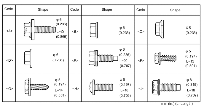
TABLE OF BOLT, SCREW AND NUT
Tech Tips
All bolts and screws relevant to installing and removing the instrument panel are shown along with their alphabetic code in the table below.
-
PRECAUTION
Note
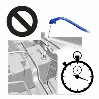
After turning the power switch off, waiting time may be required before disconnecting the cable from the negative (-) auxiliary battery terminal. Therefore, make sure to read the disconnecting the cable from the negative (-) auxiliary battery terminal notices before proceeding with work.
-
ALIGN FRONT WHEELS FACING STRAIGHT AHEAD
-
CHANGE POWER TILT AND POWER TELESCOPIC STEERING COLUMN SYSTEM SETTINGS
-
REMOVE NO. 2 DECK BOARD
-
DISCONNECT CABLE FROM NEGATIVE AUXILIARY BATTERY TERMINAL
CAUTION:
-
Wait at least 90 seconds after disconnecting the cable from the negative (-) auxiliary battery terminal to disable the SRS system.
-
If the airbag deploys for any reason, it may cause a serious accident.
Note
When disconnecting the cable, some systems need to be initialized after the cable is reconnected.
Click here
-
-
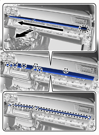
REMOVE CENTER UPPER INSTRUMENT CLUSTER FINISH PANEL
-
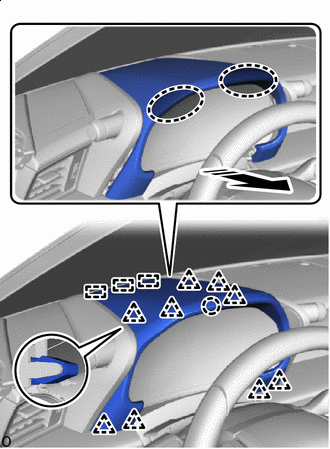

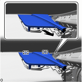
Place hands here 
Remove in this Direction Place both hands at the position shown in the illustration and pull towards the rear of the vehicle to detach the clips, claw and guides.
-
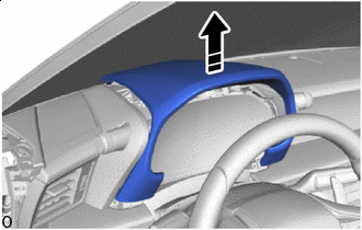
Remove in this Direction Lift up the center upper instrument cluster finish panel as shown in the illustration to remove it.
-
-
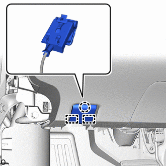
REMOVE METER HOOD SUB-ASSEMBLY
-
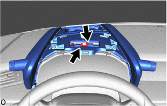
Disconnect the 2 connectors.
-
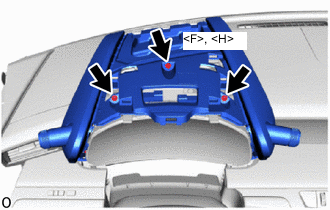
Remove the screw <F> or <H> and 2 screws.
-
Remove the 2 screws.
-
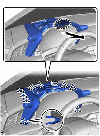
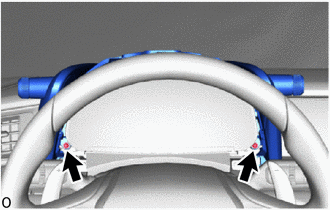
Place hand here Remove in this Direction Pull the part in the removal direction shown in the illustration to detach the clips and guides and remove the meter hood sub-assembly.
-
-
REMOVE COMBINATION METER ASSEMBLY
-
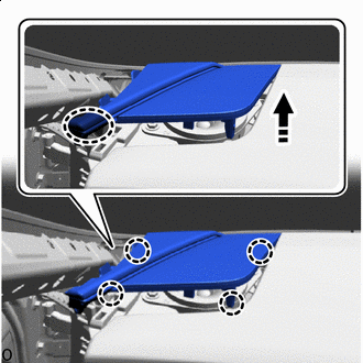
REMOVE FRONT DOOR SCUFF PLATE LH
-
Place hand here Remove in this Direction Place your hand at the position shown in the illustration and open the front door scuff plate LH towards the center of the vehicle. Then, lift it up in the direction of the arrow to detach the claws and guide.
-
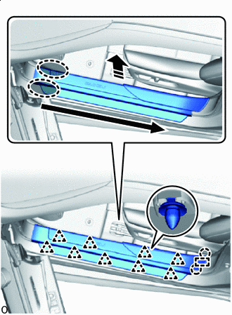
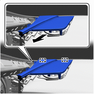
Place hands here Remove in this Direction 
Order of Removal Place both hands in the gap in the vehicle and while pulling in the direction of the arrow shown in the illustration to detach the clips, claws and guide and remove the front door scuff plate LH.
-
-
REMOVE FRONT DOOR SCUFF PLATE RH
Tech Tips
Use the same procedure described for the LH side.
-
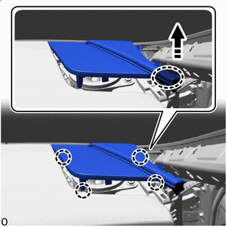
REMOVE FRONT DOOR OPENING TRIM COVER LH
-
Place hand here Remove in this Direction Place your hand at the position shown in the illustration and pull in the direction of the arrow to detach the claws and guide and remove the front door opening trim cover LH.
-
-
REMOVE FRONT DOOR OPENING TRIM COVER RH
Tech Tips
Use the same procedure described for the LH side.
-
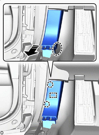
REMOVE FRONT DOOR NO. 2 OPENING TRIM COVER LH
-
Place hand here Remove in this Direction Place your hand at the position shown in the illustration and pull in the direction indicated by the arrow to detach the claws.
-
Place hand here Remove in this Direction Place your hand at the position shown in the illustration and pull in the direction of the arrow to detach the clip and claw and remove the front door No. 2 opening trim cover LH.
-
-
REMOVE FRONT DOOR NO. 2 OPENING TRIM COVER RH
-
Place hand here Remove in this Direction Place your hand at the position shown in the illustration and pull in the direction indicated by the arrow to detach the claws.
-
Place hand here Remove in this Direction Place your hand at the position shown in the illustration and pull in the direction of the arrow to detach the clip and claw and remove the front door No. 2 opening trim cover RH.
-
-
REMOVE NO. 1 INSTRUMENT PANEL UNDER COVER SUB-ASSEMBLY
-
for LHD:
-
Remove the 2 screws.
-
Remove in this Direction Detach the claws and lower the No. 1 instrument panel under cover sub-assembly in the direction of the arrow shown in the illustration.
-
Remove in this Direction Detach the claw of the arrow shown in the illustration.
-
Disconnect the connector.
-
Remove in this Direction Pull in the direction of the arrow shown in the illustration to detach the guides and remove the No. 1 instrument panel under cover sub-assembly.
-
-
for RHD:
-
Remove the 2 screws.
-
Remove in this Direction Detach the claws and lower the No. 1 instrument panel under cover sub-assembly in the direction of the arrow shown in the illustration.
-
Disconnect the connector.
-
Remove in this Direction Pull in the direction of the arrow shown in the illustration to detach the guides and remove the No. 1 instrument panel under cover sub-assembly.
-
-
-
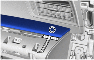
REMOVE NO. 1 GLOVE COMPARTMENT PANEL
-
Place hand here Remove in this Direction Order of Removal Place your hand at the position shown in the illustration and pull the No. 1 glove compartment panel towards the rear of the vehicle to detach the clips and remove the No. 1 glove compartment panel.
-
-
REMOVE CONSOLE BOX ASSEMBLY (for LHD)
-
REMOVE TRANSMISSION FLOOR SHIFT ASSEMBLY (for RHD)
-
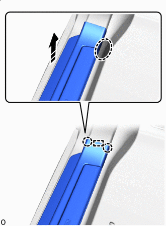
REMOVE NO. 2 INSTRUMENT PANEL GARNISH SUB-ASSEMBLY
-

Protective Tape Apply protective tape at the position shown in the illustration.
-
Insert moulding remover A at the position shown in the illustration and detach the claw.
-
Place hand here Remove in this Direction Order of Removal Place your hand in the gap and pull diagonally to the upper rear of the vehicle to detach the claws and guides and remove the No. 2 instrument panel garnish sub-assembly.
-
-
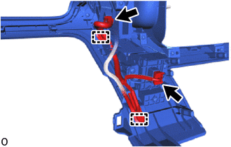
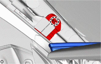
REMOVE HOOD LOCK CONTROL LEVER SUB-ASSEMBLY
-
Detach the claw and guides and remove the hood lock control lever sub-assembly from the No. 1 instrument panel safety pad sub-assembly.
-
-
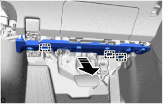
REMOVE NO. 1 INSTRUMENT PANEL SAFETY PAD SUB-ASSEMBLY
-
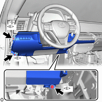
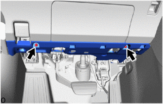
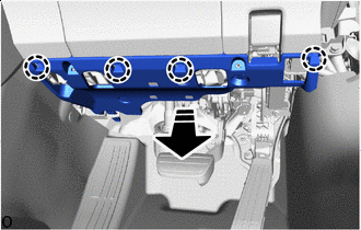
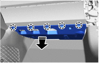
Remove the 3 bolts <E>.
-
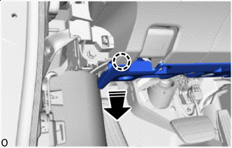
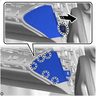
Place hand here Remove in this Direction Place your hand at the position shown in the illustration and pull in the direction indicated by the arrow to detach the claws and guide.
-
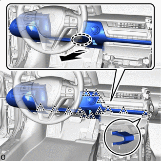
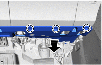
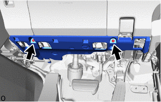
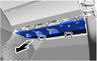
Place hand here Remove in this Direction Pull in the direction indicated by the arrow shown in the illustration to detach the clips.
-
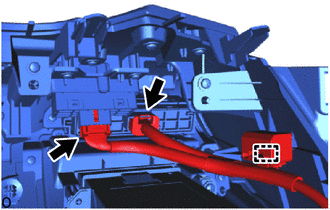
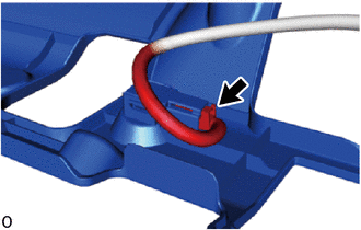
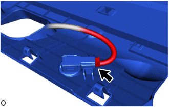
Detach the clamp and disconnect the 2 connectors.
-
Detach the clamps and disconnect the 2 connectors and remove the No. 1 instrument panel safety pad sub-assembly.
-
-
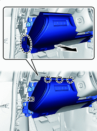
REMOVE INSTRUMENT PANEL REGISTER BEZEL
-
Place hand here Remove in this Direction Place your hand at the position shown in the illustration and pull in the direction indicated by the arrow to detach the claws.
-
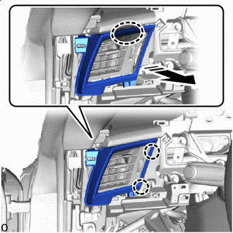
Place hand here Remove in this Direction Pull in the direction of the arrow shown in the illustration to detach the claws and remove the instrument panel register bezel.
-
-
REMOVE INTEGRATION CONTROL AND PANEL ASSEMBLY
-
REMOVE RADIO RECEIVER ASSEMBLY WITH BRACKET
-
REMOVE TELEPHONE TRANSCEIVER ASSEMBLY WITH BRACKET (w/ Telematics Transceiver)
-
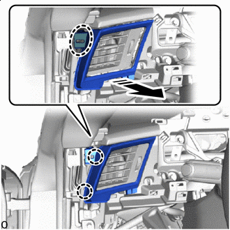
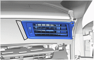
REMOVE NO. 2 INSTRUMENT PANEL REGISTER ASSEMBLY
-
Protective Tape Apply protective tape at the position shown in the illustration.
-
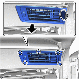
Place hand here Remove in this Direction Pull in the direction of the arrow shown in the illustration to detach the claws.
-
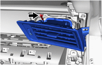
Pull the No. 2 instrument panel register assembly and disconnect the connector and remove the No. 2 instrument panel register assembly.
-
-
REMOVE NO. 2 INSTRUMENT PANEL UNDER COVER SUB-ASSEMBLY
-
Remove in this Direction Detach the claws and lower the No. 2 instrument panel under over sub-assembly in the direction of the arrow shown in the illustration.
-
Disconnect the connector.
-
Remove in this Direction Pull in the direction of the arrow shown in the illustration to detach the guides and remove the No. 2 instrument panel under cover sub-assembly.
-
-
REMOVE NO. 2 GLOVE COMPARTMENT PANEL
-
Place hand here Remove in this Direction Place your hand at the position shown in the illustration and pull the No. 2 glove compartment panel towards the outside of the vehicle to detach the claws and remove the No. 2 glove compartment panel.
-
w/ Airbag Cut Off Switch:
Disconnect the connector.
-
-
REMOVE LOWER NO. 2 INSTRUMENT PANEL AIRBAG ASSEMBLY
-
REMOVE GLOVE COMPARTMENT DOOR ASSEMBLY
-
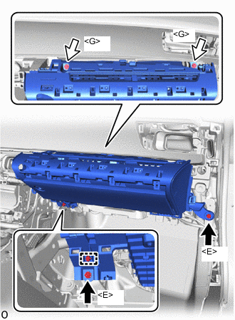
Bolt <E> 
Screw <G> Detach the clamp.
-
Remove the 2 bolts <E> and 2 screws <G>.
-
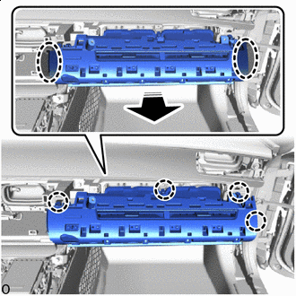
Place hand here Remove in this Direction Place your hand at the position shown in the illustration and pull in the direction indicated by the arrow to detach the claws.
-
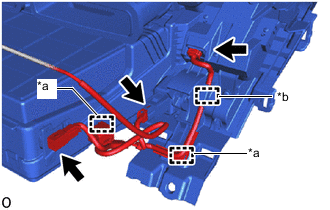
*a Clamp *b Hook Detach the clamps and hook and remove the glove compartment box assembly.
-
Disconnect the 3 connectors.
-
-
REMOVE MULTI-DISPLAY
-
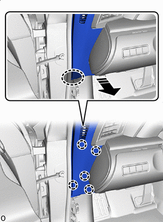
REMOVE FRONT PILLAR GARNISH LH
-
REMOVE FRONT PILLAR GARNISH RH
Tech Tips
Use the same procedure described for the LH side.
-
REMOVE NO. 1 INSTRUMENT PANEL SPEAKER PANEL SUB-ASSEMBLY
-
for LHD:
-
Disconnect the 2 connectors.
-
Detach the claw and remove the connector holder.
-
-
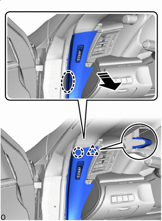
Place hand here Remove in this Direction Lift up the part in the removal direction shown in the illustration to detach the claws.
-
Remove in this Direction Pull in the direction of the arrow shown in the illustration to detach the guides and remove the No. 1 instrument panel speaker panel sub-assembly.
-
-
REMOVE NO. 2 INSTRUMENT PANEL SPEAKER PANEL SUB-ASSEMBLY
-
for RHD:
-
Disconnect the 2 connectors.
-
Detach the claw and remove the connector holder.
-
-
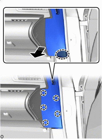
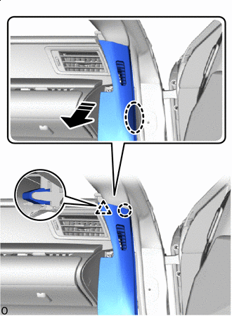
Place hand here Remove in this Direction Lift up the part in the removal direction shown in the illustration to detach the claws.
-
Remove in this Direction Pull in the direction of the arrow shown in the illustration to detach the guides and remove the No. 2 instrument panel speaker panel sub-assembly.
-
-
REMOVE FRONT NO. 1 SPEAKER ASSEMBLY
-
REMOVE LOWER NO. 1 INSTRUMENT PANEL AIRBAG ASSEMBLY
-
REMOVE STEERING WHEEL SWITCH HOUSING
-
REMOVE NO. 2 AIR DUCT
-
Remove in this Direction Remove the 2 bolts and No. 2 air duct in the direction of the arrow shown in the illustration.
-
-
REMOVE DOUBLE LOCK DOOR CONTROL RELAY ASSEMBLY (w/ Double Locking System)
-
REMOVE HEATER TO REGISTER CENTER SUB DUCT
-
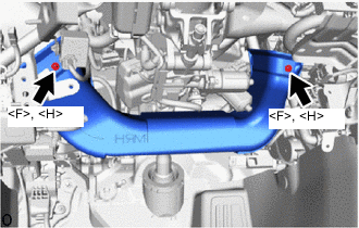
Remove the 2 screws <F> or <H> and heater to register center sub duct.
-
-
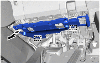
REMOVE NO. 3 INSTRUMENT PANEL TO COWL BRACE SUB-ASSEMBLY
-
for LHD:
-
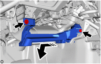
*A w/ Clearance Sonar System Bolt <A> Nut <B> Detach the clamps.
-
Remove the bolt <A>, nut <B> and No. 3 instrument panel to cowl brace sub-assembly.
-
-
for RHD:
-
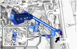
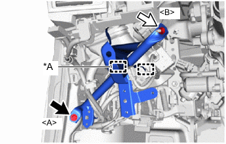
*A w/ Clearance Sonar System *1 DLC3 Bolt <A> Nut <B> Detach the clamps.
-
Detach the claws and remove the DLC3.
-
Remove the bolt <A>, nut <B> and No. 3 instrument panel to cowl brace sub-assembly.
-
-
-
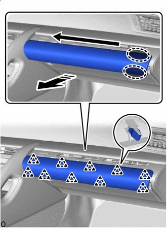
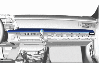
REMOVE INSTRUMENT PANEL SAFETY PAD SUB-ASSEMBLY
-
Disconnect airbag connector:
-
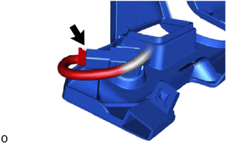
Push down the housing lock and slide the CPA to release the lock.
Note
Do not pull while holding the wire harness.
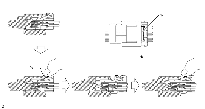
*a Housing Lock *b CPA *c Disconnect the connector lock - - -
With the housing lock pushed down again, slide the CPA to disconnect the airbag connector.
-
After disconnecting the airbag connector, check that the CPA is positioned further back than the housing.
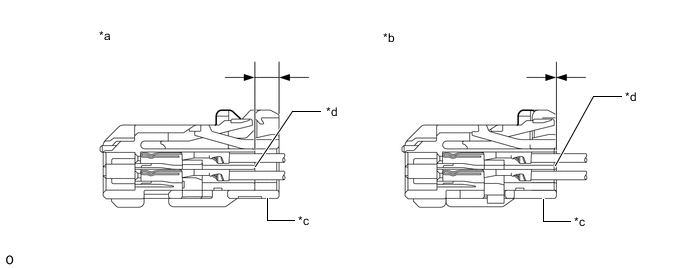
*a CORRECT *b INCORRECT *c CPA *d Housing
-
-
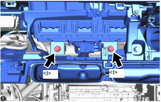
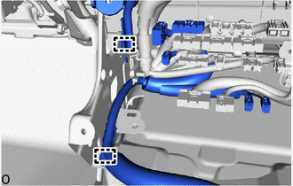
Remove the 2 bolts <I>.
-
for LHD:
-
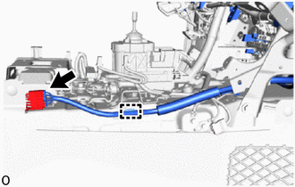
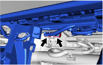
Detach the clamp and disconnect the connector.
-
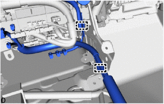
Detach the clamps.
-
Disconnect the connector.
-
-
for RHD:
-
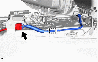
Detach the clamp and disconnect the connector.
-
Detach the clamps.
-
Disconnect the connector.
-
-
Disconnect the 2 connectors.
-
for LHD:
-
Detach the claws and remove the cooler thermistor (recirculated air temperature) from the instrument panel safety pad sub-assembly.
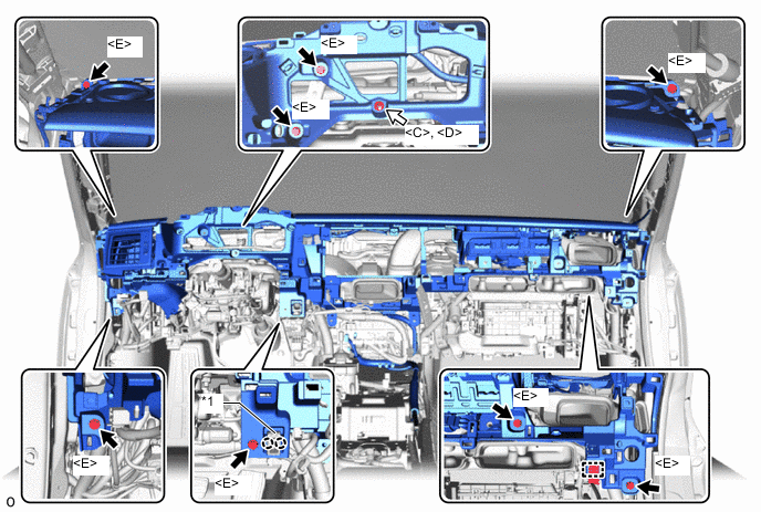
*1 Cooler Thermistor (Recirculated Air Temperature) - - Bolt <E> Nut <C> or <D> -
Detach the clamp.
-
Remove the 8 bolts <E>, and nut <C> or <D>.
-
-
for RHD:
-
Detach the claws and remove the cooler thermistor (recirculated air temperature) from the instrument panel safety pad sub-assembly.
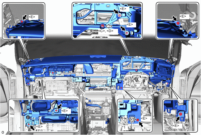
*1 Cooler Thermistor (Recirculated Air Temperature) - - Bolt <E> Nut <C> or <D> -
Remove the 8 bolts <E>, and nut <C> or <D>.
-
-
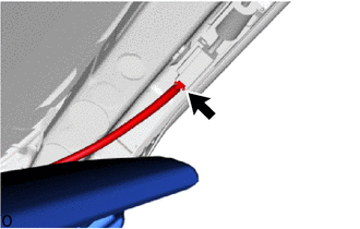
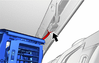
Pull as shown in the illustration to detach the guides.
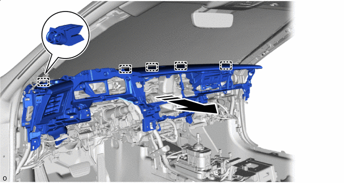
Remove in this Direction - - -
Lift up the instrument panel safety pad sub-assembly as shown in the illustration to remove it.
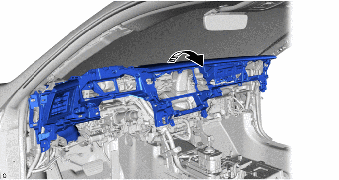
Remove in this Direction - -
-