HEATER WATER PUMP INSTALLATION
CAUTION / NOTICE / HINT
Tech Tips
-
Use the same procedure for RHD and LHD vehicles.
-
The procedure listed below is for LHD vehicles.
PROCEDURE
-
INSTALL HEATER ACCESSORY ASSEMBLY
-
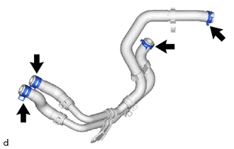
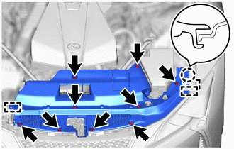
Attach the 4 hose clips to the water pipe sub-assembly.
-
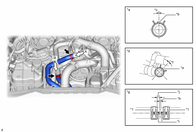
Connect water pipe sub-assembly with its marking aligned as shown in the illustration and install the 2 hose clips within the range shown in the illustration.
Note
-
Do not apply excessive force to the water pipe sub-assembly.
-
Install the clips 2 to 5 mm (0.0787 to 0.1969 in.) away from the end of the hose.
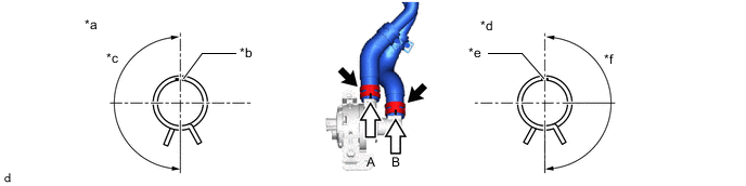
*a View A *b Marking (Green) *c Hose Clip Installation Angle (165 to 195°) *d View B *e Marking (White) *f Hose Clip Installation Angle (165 to 195°) -
-
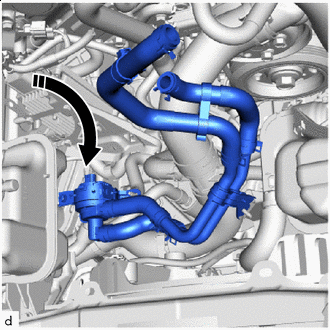

Insert in this Direction Insert the heater accessory assembly (with water pipe sub-assembly) into the vehicle from engine room as shown in the illustration.
-
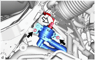

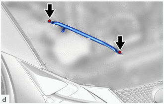
Nut 
Connector Install the heater accessory assembly (with water pipe sub-assembly) with the 2 nuts.
- Torque:
- 8.0 N*m { 82 kgf*cm, 71 in.*lbf }
-
Connect the connector.
-
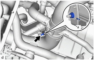
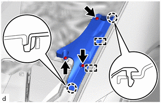
*a Stopper Install the nut.
- Torque:
- 8.0 N*m { 82 kgf*cm, 71 in.*lbf }
Note
Install with a stopper on the seating surface of the transmission oil cooler bracket.
-
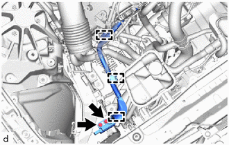
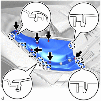
Connect water pipe sub-assembly with its marking aligned as shown in the illustration and install the 2 hose clips within the range shown in the illustration.
Note
-
Do not apply excessive force to the water pipe sub-assembly.
-
Insert the hose until it bulges but without it sticking out.
*1 Hose Clip - - *a View A *b Marking (Blue) *c Hose Clip Installation Angle (-15 to 15°) *d View B *e Marking (Yellow) *f Hose Clip Installation Angle (-15 to 15°) *g Hose Connector Detail *h Bulge *i Marking *j Hose Clip Installation Range (3 to 7 mm (0.1181 to 0.2756 in.)) -
-
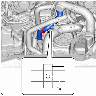
*1 Clamp *a Marking Attach the clamp as shown in the illustration.
Note
Make sure the marking is hidden in the clamp.
-
-
INSTALL OIL PUMP MOTOR CONTROLLER ASSEMBLY
-
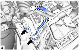
*a Clamp (A) *b Clamp (B) Install the oil pump motor controller assembly with the 2 nuts.
- Torque:
- 8.5 N*m { 87 kgf*cm, 75 in.*lbf }
-
for LHD:
-
Attach the clamp (A) and (B).
-
-
for RHD:
-
Attach the clamp (B).
-
-
Attach the clamp.
-
Connect the ground wire with the 2 bolts.
- Torque:
- 10 N*m { 102 kgf*cm, 7 ft.*lbf }
-
-
INSTALL AIR CLEANER ASSEMBLY
-
INSTALL NO. 1 AIR CLEANER INLET
-
INSTALL RADIATOR SUPPORT TO CROSSMEMBER BRACE SUB-ASSEMBLY RH
-
Install the radiator support to crossmember brace sub-assembly RH with the 2 bolts.
- Torque:
- 49 N*m { 500 kgf*cm, 36 ft.*lbf }
-
-
ADD ENGINE COOLANT
-
INSPECT FOR COOLANT LEAK
-
INSTALL NO. 2 ENGINE UNDER COVER ASSEMBLY
-
INSTALL NO. 1 ENGINE UNDER COVER ASSEMBLY
-
INSTALL LOWER RADIATOR AIR DEFLECTOR
-
Attach the claw and guide to install the lower radiator air deflector.
-
Install the 9 clips.
-
-
INSTALL ENGINE ROOM SIDE COVER LH
-
Attach the claw and guide to install the engine room side cover LH.
-
Install the 3 clips.
-
-
INSTALL RADIATOR SUPPORT TO FRAME SEAL RH
-
Attach the claw and guide to install the radiator support to frame seal RH.
-
Install the 6 clips.
-
-
INSTALL V-BANK COVER SUB-ASSEMBLY