HEATER WATER PUMP REMOVAL
CAUTION / NOTICE / HINT
Tech Tips
-
Use the same procedure for RHD and LHD vehicles.
-
The procedure listed below is for LHD vehicles.
PROCEDURE
-
REMOVE V-BANK COVER SUB-ASSEMBLY
-
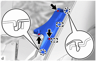
REMOVE RADIATOR SUPPORT TO FRAME SEAL RH
-
Remove the 6 clips.
-
Detach the claw and guide and remove the radiator support to frame seal RH.
-
-
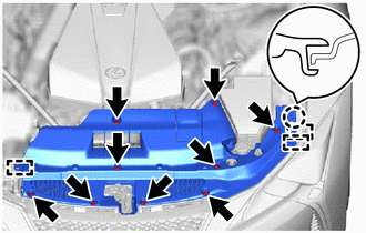
REMOVE ENGINE ROOM SIDE COVER LH
-
Remove the 3 clips.
-
Detach the claw and guide and remove the engine room side cover LH.
-
-
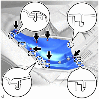
REMOVE LOWER RADIATOR AIR DEFLECTOR
-
Remove the 9 clips.
-
Detach the claw and guide and remove the lower radiator air deflector.
-
-
REMOVE NO. 1 ENGINE UNDER COVER ASSEMBLY
-
REMOVE NO. 2 ENGINE UNDER COVER ASSEMBLY
-
DRAIN ENGINE COOLANT
-
REMOVE RADIATOR SUPPORT TO CROSSMEMBER BRACE SUB-ASSEMBLY RH
-
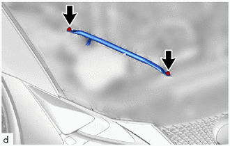
Remove the 2 bolts and radiator support to crossmember brace sub-assembly RH.
-
-
REMOVE NO. 1 AIR CLEANER INLET
-
REMOVE AIR CLEANER ASSEMBLY
-
REMOVE OIL PUMP MOTOR CONTROLLER ASSEMBLY
-
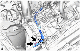
Remove the 2 bolts.
-
Detach the clamp and disconnect the ground wire.
-
for LHD:
-
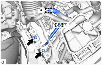
*a Clamp (A) *b Clamp (B) Detach the clamp (A) and (B).
-
-
for RHD:
-
Detach the clamp (B).
-
-
Remove the 2 nuts.
-
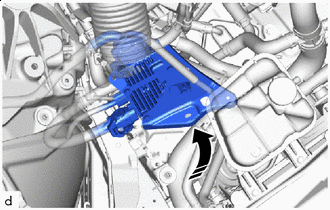

Movement Direction Move the oil pump motor controller assembly to the position shown in the illustration.
-
-
REMOVE HEATER ACCESSORY ASSEMBLY
-
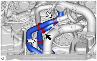

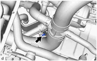
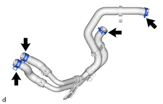
Clamp 
Clip Disconnect the clamps shown in the illustration.
-
Using pliers, grip the claws of the 2 hose clips and slide the hose clip to disconnect the water pipe sub-assembly.
Note
-
Do not apply excessive force to the water pipe sub-assembly.
-
Prepare a drain pan or cloth in case the coolant leaks.
-
-
Remove the nut.
-
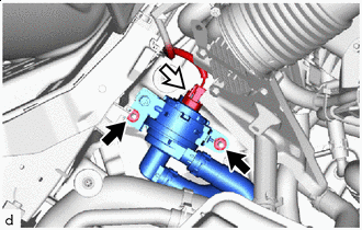
Nut Connector Disconnect the connector.
-
Remove the 2 nuts.
-
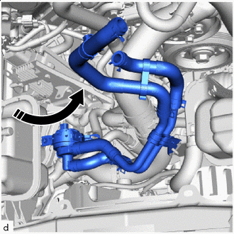
Remove in this Direction Move the heater accessory assembly (with water pipe sub-assembly) to the center of the engine room and remove it as shown in the illustration.
-
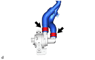
Using pliers, grip the claws of the 2 hose clips and slide the hose clip to remove the water pipe sub-assembly.
Note
-
Do not apply excessive force to the water pipe sub-assembly.
-
Prepare a drain pan or cloth in case the coolant leaks.
-
-
Remove the 4 hose clips from the water pipe sub-assembly.
-