FRONT CONSOLE BOX INSTALLATION
CAUTION / NOTICE / HINT
Tech Tips
-
Use the same procedure as for the LHD and RHD vehicles.
-
The procedure listed below is for the LHD vehicles.
PROCEDURE
-
INSTALL CONSOLE BOX ASSEMBLY
-
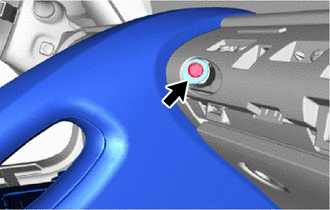
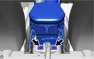
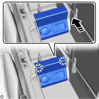
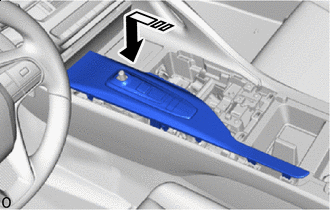
Align the guides and attach the claws and clip in the direction of the arrow shown in the illustration to temporarily install the console box assembly.
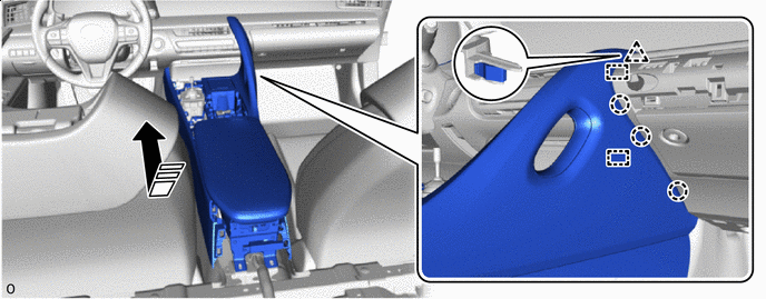

Install in this Direction - - -
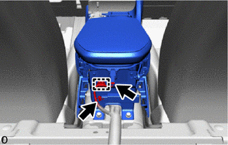
Install the bolt.
-
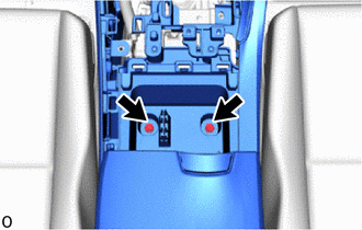
Install the 2 bolts.
-
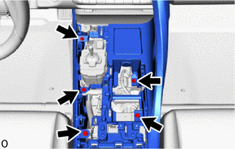
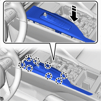
Install the 5 bolts.
-
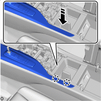
Install the console box assembly with the 2 bolts.
-
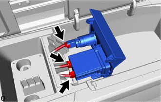
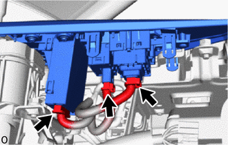
Connect the 2 connectors and attach the clamp.
-
-
INSTALL NO. 1 GLOVE COMPARTMENT PANEL
-
INSTALL EQUIPMENT SET PANEL
-
Connect the 3 connectors.
-
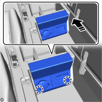
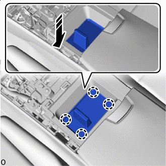
Install in this Direction Attach the claws in the direction of the arrow shown in the illustration.
-
Install in this Direction Attach the claws in the direction of the arrow shown in the illustration to install the equipment set panel.
-
-
INSTALL EQUIPMENT SET PANEL COVER
-
Install in this Direction Attach the claws in the direction of the arrow shown in the illustration to install the equipment set panel cover.
-
-
INSTALL LOWER CONSOLE BOX
-
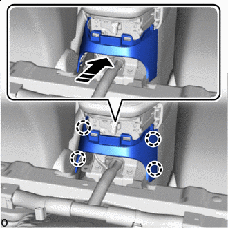
Install in this Direction Attach the claws in the direction of the arrow shown in the illustration to install the lower console box.
-
-
INSTALL UPPER CONSOLE BOX
-
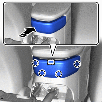
Install in this Direction Align the guide and attach the claws in the direction of the arrow shown in the illustration to install the upper console box.
-
-
INSTALL REAR SEAT CUSHION LOCK HOOK
-
INSTALL REAR SEAT CUSHION ASSEMBLY
-
INSTALL SHIFTING HOLE COVER ASSEMBLY
-
Connect the 3 connectors.
-
Install in this Direction Set the shifting hole cover assembly on the shift lever in the direction of the arrow shown in the illustration.
-
Install in this Direction Attach the claws in the direction of the arrow shown in the illustration.
-
Install in this Direction Attach the claws in the direction of the arrow shown in the illustration to install the shifting hole cover assembly.
-
Remove the protective tape.
-
-
INSTALL SHIFT LEVER KNOB SUB-ASSEMBLY
-
INSTALL RADIO REMOTE TUNING SWITCH ASSEMBLY
-
INSTALL REAR CONSOLE BOX POCKET