AIR CONDITIONING SYSTEM Air Vent Temperature does not Change and Right Vent is Different from Left and Vice Versa (Same Left/Right Temperature Setting)
DESCRIPTION
If there is a difference in temperature between the left and right air outlet while dual mode is ON, the following causes are possible.
| Malfunction Status | Factor |
|---|---|
| There is a difference in temperature between the left and right air outlet (while cooling operation) |
|
| There is a difference in temperature between the left and right air outlet (while heater operation) |
|
WIRING DIAGRAM
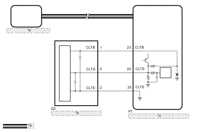
| *a | Air Conditioning Amplifier Assembly |
| *b | Automatic Light Control Sensor |
| *c | Main Body ECU (Multiplex Network Body ECU) |
| *d | CAN Communication Line |
CAUTION / NOTICE / HINT
Note
-
If DTC B1244 is output, troubleshoot for DTC B1244 first.
-
Before replacing the main body ECU (multiplex network body ECU), refer to Service Bulletin.
PROCEDURE
-
CHECK MALFUNCTION STATUS
Result Result Proceed to While cooling A While heater B
B 
PERFORM AIR OMMISION OF COOLANT Click here
A 
-
CHECK REFRIGERANT SHORTAGE
-
Prepare the vehicle according to the table below.
Measurement Condition: Item Condition A/C switch On Ambient temperature* 0 to 49°C (32 to 120°F) Blower speed HI *: If the ambient temperature is not within the range shown, do not perform this check.
-
Connect the GTS to the DLC3.
-
Turn the power switch on (READY).
-
Turn the GTS on.
-
Enter the following menus: Body Electrical / Air Conditioner / Utility / Refrigerant Gas Volume Check.
Body Electrical > Air Conditioner > UtilityTester Display Refrigerant Gas Volume Check Result Result Amount of Refrigerant Refrigerant shortage Insufficient or leakage Refrigerant correct Correct OK "Refrigerant correct" is displayed on GTS. Result Proceed to OK NG
NG 
CHARGE SYSTEM WITH REFRIGERANT for HFC-134a (R134a): Click here for HFO-1234yf (R1234yf): Click here
OK
-
-
PERFORM ACTIVE TEST USING GTS (SERVO PULSE)
-
Connect the GTS to the DLC3.
-
Turn the power switch on (IG).
-
Turn the GTS on.
-
Enter the following menus: Body Electrical / Air Conditioner / Active Test.
-
Check the operation by referring to the table below.
Body Electrical > Air Conditioner > Active TestTester Display Measurement Item Control Range Diagnostic Note Air Mix Servo Targ Pulse(D)
-
No. 1 air conditioning radiator damper servo sub-assembly (driver side upper air mix) operation
for LHD:
-
No. 4 air conditioning radiator damper servo sub-assembly (driver side upper air mix) operation
for RHD:
Min.: 128
Max.: 383
Operates between 186 and 258 pulses Air Mix Servo Targ Pulse(P) No. 2 air conditioning radiator damper servo sub-assembly (front passenger side upper air mix) operation Min.: 128
Max.: 383
Operates between 154 and 258 pulses
Body Electrical > Air Conditioner > Active TestTester Display Air Mix Servo Targ Pulse(D)
Body Electrical > Air Conditioner > Active TestTester Display Air Mix Servo Targ Pulse(P) OK Damper servo motor is operated. Result Proceed to OK NG -
NG
GO TO DTC OF APPLICABLE SERVO MOTOR OPERATING ABNORMALLY Click here
OK
-
-
CHECK HARNESS AND CONNECTOR (AUTOMATIC LIGHT CONTROL SENSOR - MAIN BODY ECU (MULTIPLEX NETWORK BODY ECU))
-
Disconnect the Q3 automatic light control sensor connector.
-
Disconnect the P7 main body ECU (multiplex network body ECU) connector.
-
Measure the resistance according to the value(s) in the table below.
Standard Resistance Tester Connection Condition Specified Condition Q3-1 (CLTB) - P7-23 (CLTB) Always Below 1 Ω Q3-2 (CLTE) - P7-25 (CLTE) Always Below 1 Ω Q3-4 (CLTS) - P7-24 (CLTS) Always Below 1 Ω Q3-1 (CLTB) or P7-23 (CLTB) - Other terminals and body ground Always 10 kΩ or higher Q3-2 (CLTE) or P7-25 (CLTE) - Other terminals and body ground Always 10 kΩ or higher Q3-4 (CLTS) or P7-24 (CLTS) - Other terminals and body ground Always 10 kΩ or higher Result Proceed to OK NG
NG
REPAIR OR REPLACE HARNESS OR CONNECTOR
OK
-
-
INSPECT AUTOMATIC LIGHT CONTROL SENSOR
-
Remove the automatic light control sensor.
-
Inspect the automatic light control sensor.
Result Proceed to OK NG
OK
GO TO ON-VEHICLE INSPECTION Click here
NG
REPLACE AUTOMATIC LIGHT CONTROL SENSOR Click here
-
-
PERFORM AIR OMMISION OF COOLANT
Result Proceed to NEXT
NEXT
-
CHECK OPERATION (AIR CONDITIONING SYSTEM)
-
Check that there is not a difference in temperature between the left and right air outlet.
OK There is not a difference in temperature between the left and right air outlet. Result Proceed to OK NG
OK
END (FAILURE DUE TO AIR ENTERING COOLANT)
NG
-
-
PERFORM ACTIVE TEST USING GTS (SERVO PULSE)
-
Connect the GTS to the DLC3.
-
Turn the power switch on (IG).
-
Turn the GTS on.
-
Enter the following menus: Body Electrical / Air Conditioner / Active Test.
-
Check the operation by referring to the table below.
Body Electrical > Air Conditioner > Active TestTester Display Measurement Item Control Range Diagnostic Note Air Mix Servo Targ Pulse(D)
-
No. 1 air conditioning radiator damper servo sub-assembly (driver side upper air mix) operation
for LHD:
-
No. 4 air conditioning radiator damper servo sub-assembly (driver side upper air mix) operation
for RHD:
Min.: 128
Max.: 383
Operates between 186 and 258 pulses Air Mix Servo Targ Pulse(P) No. 2 air conditioning radiator damper servo sub-asembly (front passenger side upper air mix) operation Min.: 128
Max.: 383
Operates between 154 and 258 pulses
Body Electrical > Air Conditioner > Active TestTester Display Air Mix Servo Targ Pulse(D)
Body Electrical > Air Conditioner > Active TestTester Display Air Mix Servo Targ Pulse(P) OK Damper servo motor is operated. Result Proceed to OK NG -
NG
GO TO DIAGNOSTIC TROUBLE CODE CHART (FOR SERVO MOTOR OF APPLICABLE ABNORMAL OPERATION) Click here
OK
-
-
INSPECT HEATER ACCESSORY ASSEMBLY
-
Remove the heater accessory assembly.
-
Inspect the heater accessory assembly.
Result Proceed to OK NG
OK
REPLACE HEATER RADIATOR UNIT SUB-ASSEMBLY Click here
NG
GO TO HEATER WARTER PUMP CIRCUIT Click here
-