AIR CONDITIONING SYSTEM Operation not Accepted Even If Air Conditioning Switch is Operated
DESCRIPTION
If the air conditioning system does not operate even when the integration control and panel assembly is operated, the following causes are possible.
| Malfunction Status | Factor |
|---|---|
| Operations are never accepted by the integration control and panel assembly
|
|
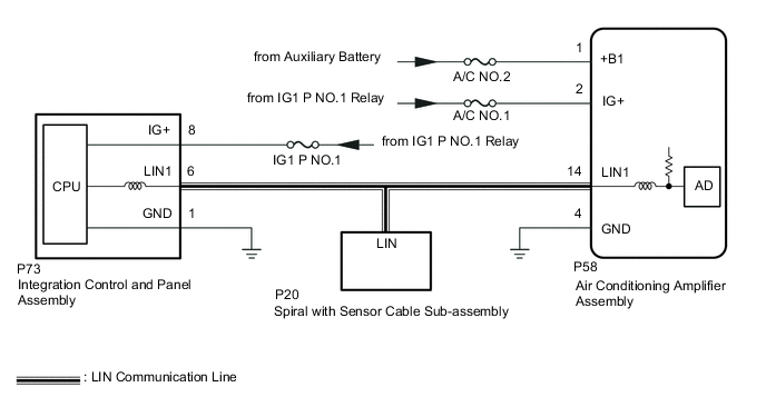
WIRING DIAGRAM
CAUTION / NOTICE / HINT
Note
-
Inspect the fuses for circuits related to this system before performing the following procedure.
-
If DTC B14B7 is output at the same time, troubleshoot for DTC B14B7 first.
-
The vehicle is equipped with a Supplemental Restraint System (SRS) which includes components such as airbags. Before servicing (including removal or installation of parts), be sure to read the precaution for Supplemental Restraint System.
PROCEDURE
-
CHECK FOR DTC
-
Check for DTCs.
Body Electrical > Air Conditioner > Trouble CodesOK DTC B14B2 is not output. Result Proceed to OK NG
NG 
GO TO DTC B14B2 Click here
OK 
-
-
CHECK HARNESS AND CONNECTOR (AIR CONDITIONING AMPLIFIER ASSEMBLY - BATTERY AND BODY GROUND)
-
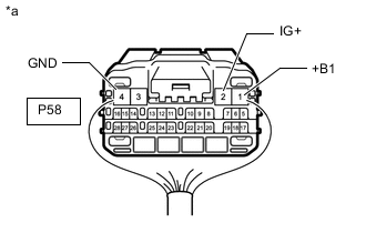
*a Rear view of wire harness connector
(to Air Conditioning Amplifier Assembly)
Disconnect the air conditioning amplifier assembly connector.
-
Measure the resistance according to the value(s) in the table below.
Standard Resistance Tester Connection Condition Specified Condition P58-4 (GND) - Body ground Always Below 1 Ω -
Measure the voltage according to the value(s) in the table below.
Standard Voltage Tester Connection Switch Condition Specified Condition P58-1 (+B1) - Body ground Power switch off 11 to 14 V P58-2 (IG+) - Body ground Power switch on (IG) 11 to 14 V Power switch off Below 1 V Result Proceed to OK NG
OK
REPLACE AIR CONDITIONING AMPLIFIER ASSEMBLY Click here
NG
REPAIR OR REPLACE HARNESS OR CONNECTOR
-