AIR CONDITIONING SYSTEM Cooling is Poor
DESCRIPTION
If the cooling air is poor (cooling air is discharged), the following causes are possible.
| Malfunction Status | Factor |
|---|---|
|
|
WIRING DIAGRAM
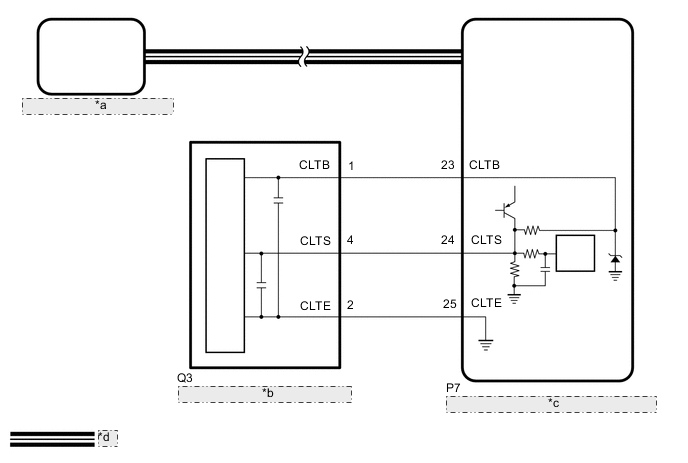
| *a | Air Conditioning Amplifier Assembly |
| *b | Automatic Light Control Sensor |
| *c | Main Body ECU (Multiplex Network Body ECU) |
| *d | CAN Communication Line |
PROCEDURE
-
CHECK ECO DRIVE MODE OPERATION
-
Confirm setup of the ECO drive mode and turn it off if it becomes ON.
Tech Tips
-
When ECO drive mode is on, the air conditioning amplifier assembly ensures a minimum level of air conditioning control based on certain conditions, thereby contributing to improved fuel efficiency. Accordingly, explain to customers that the air volume will be weaker in these situations.
Control Airflow Control Automatically switches the air inlet port to the internal air circulation mode when the outside air temperature is equal to or higher than a predetermined temperature and reduces the power consumption. Air Inlet Control Sets the blower level in AUTO mode lower than normal, and suppresses the power consumption. -
If combination switch assembly is malfunctioning, perform diagnosis on the ECO switch circuit.
Result Proceed to NEXT -
NEXT 
-
-
CHECK REFRIGERANT PRESSURE
-
Connect the GTS to the DLC3.
-
Turn the power switch on (IG).
-
Turn the GTS on.
-
Enter the following menus: Body Electrical / Air Conditioner / Data List.
-
Read the Data List according to the display on the GTS.
Body Electrical > Air Conditioner > Data ListTester Display Measurement Item Range Normal Condition Diagnostic Note Regulator Pressure Sensor Air conditioner pressure sensor Min.: -0.4566 MPaG
Max.: 3.2943 MPaG
Actual refrigerant pressure displayed
-
Refrigerant line (gad leak etc.)
-
Air conditioner pressure sensor system malfunction
Body Electrical > Air Conditioner > Data ListTester Display Regulator Pressure Sensor -
-
Install a manifold gauge set.
-
for HFC-134a (R134a): Click here
-
for HFO-1234yf (R1234yf): Click here
-
-
Read the manifold gauge pressure when the following conditions are met.
-
Prepare the vehicle according to the table below.
Measurement Condition: Item Condition Vehicle doors Fully open Temperature setting MAX COLD Blower speed HI A/C switch On Recirculation/fresh switch RECIRCULATION Interior temperature 25 to 35°C (77 to 95°F)
Standard Pressure Low pressure side 150 to 250 kPa (1.5 to 2.5 kgf/cm2, 22 to 36 psi) High pressure side 1370 to 1570 kPa (14 to 16 kgf/cm2, 199 to 228 psi) -
-
Compare the values displayed in the Data List and on the manifold gauge.
OK The values displayed in the Data List and on the manifold gauge match. Result Proceed to OK NG
NG 
CHARGE SYSTEM WITH REFRIGERANT for HFC-134a (R134a): Click here for HFO-1234yf (R1234yf): Click here
OK
-
-
PERFORM ACTIVE TEST USING GTS (SERVO PULSE)
-
Connect the GTS to the DLC3.
-
Turn the power switch on (IG).
-
Turn the GTS on.
-
Enter the following menus: Body Electrical / Air Conditioner / Active Test.
-
Check the operation by referring to the table below.
Body Electrical > Air Conditioner > Active TestTester Display Measurement Item Control Range Diagnostic Note Air Mix Servo Targ Pulse(D)
-
No. 1 air conditioning radiator damper servo sub-assembly (driver side upper air mix) operation
for LHD:
-
No. 4 air conditioning radiator damper servo sub-assembly (driver side upper air mix) operation
for RHD:
Min.: 128
Max.: 383
Operates between 186 and 258 pulses Air Mix Servo Targ Pulse(P) No. 2 air conditioning radiator damper servo sub-assembly (front passenger side upper air mix) operation Min.: 128
Max.: 383
Operates between 154 and 258 pulses
Body Electrical > Air Conditioner > Active TestTester Display Air Mix Servo Targ Pulse(D)
Body Electrical > Air Conditioner > Active TestTester Display Air Mix Servo Targ Pulse(P) OK Damper servo motor is operated. Result Proceed to OK NG -
NG
GO TO DTC OF APPLICABLE SERVO MOTOR OPERATING ABNORMALLY Click here
OK
-
-
CHECK HARNESS AND CONNECTOR (AUTOMATIC LIGHT CONTROL SENSOR - MAIN BODY ECU (MULTIPLEX NETWORK BODY ECU))
-
Disconnect the Q3 automatic light control sensor connector.
-
Disconnect the P7 main body ECU (multiplex network body ECU) connector.
-
Measure the resistance according to the value(s) in the table below.
Standard Resistance Tester Connection Condition Specified Condition Q3-1 (CLTB) - P7-23 (CLTB) Always Below 1 Ω Q3-2 (CLTE) - P7-25 (CLTE) Always Below 1 Ω Q3-4 (CLTS) - P7-24 (CLTS) Always Below 1 Ω Q3-1 (CLTB) or P7-23 (CLTB) - Other terminals and body ground Always 10 kΩ or higher Q3-2 (CLTE) or P7-25 (CLTE) - Other terminals and body ground Always 10 kΩ or higher Q3-4 (CLTS) or P7-24 (CLTS) - Other terminals and body ground Always 10 kΩ or higher Result Proceed to OK NG
NG
REPAIR OR REPLACE HARNESS OR CONNECTOR
OK
-
-
INSPECT AUTOMATIC LIGHT CONTROL SENSOR
-
Remove the automatic light control sensor.
-
Inspect the automatic light control sensor.
Result Proceed to OK NG
OK
GO TO ON-VEHICLE INSPECTION Click here
NG
REPLACE AUTOMATIC LIGHT CONTROL SENSOR Click here
-