AIR CONDITIONING SYSTEM Blower Motor Circuit
DESCRIPTION
The blower motor with fan sub-assembly reads the signal from the air conditioning amplifier assembly and controls operation and speed changes of the blower motor.
If the blower air volume is weak, or there are any other blower malfunctions such as the temperature or air volume cannot be changed, the following causes are possible.
| Malfunction Status | Factor |
|---|---|
|
|
WIRING DIAGRAM
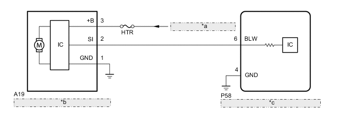
| *a | from Auxiliary Battery |
| *b | Blower with Fan Motor Sub-assembly |
| *c | Air Conditioning Amplifier Assembly |
CAUTION / NOTICE / HINT
Note
Inspect the fuses for circuits related to this system before performing the following procedure.
PROCEDURE
-
PERFORM ACTIVE TEST USING GTS (BLOWER MOTOR)
-
Connect the GTS to the DLC3.
-
Turn the power switch on (IG).
-
Turn the GTS on.
-
Enter the following menus: Body Electrical / Air Conditioner / Active Test.
-
Perform the Active Test according to the display on the GTS.
Body Electrical > Air Conditioner > Active TestTester Display Measurement Item Control Range Diagnostic Note Blower Motor Blower with fan motor sub-assembly Min.: 0
Max.: 31
-
Body Electrical > Air Conditioner > Active TestTester Display Blower Motor OK Blower with fan motor sub-assembly is operated. Result Proceed to OK NG
NG 
GO TO STEP 5 Click here
OK 
-
-
CHECK HARNESS AND CONNECTOR (BLOWER WITH FAN MOTOR SUB-ASSEMBLY - BATTERY AND BODY GROUND)
-
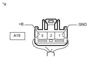
*a Front view of wire harness connector
(to Blower with Fan Motor Sub-assembly)
Disconnect the blower with fan motor sub-assembly connector.
-
Measure the resistance according to the value(s) in the table below.
Standard Resistance Tester Connection Condition Specified Condition A19-1 (GND) - Body ground Always Below 1 Ω -
Measure the voltage according to the value(s) in the table below.
Standard Resistance Tester Connection Switch Condition Specified Condition A19-3 (+B) - Body ground Power switch off 11 to 14 V Result Proceed to OK NG
NG 
REPAIR OR REPLACE HARNESS OR CONNECTOR
OK
-
-
CHECK HARNESS AND CONNECTOR (AIR CONDITIONING AMPLIFIER ASSEMBLY - BLOWER WITH FAN MOTOR SUB-ASSEMBLY)
-
Disconnect the P58 air conditioning amplifier assembly connector.
-
Disconnect the A19 blower with fam motor sub-assemblyconnector.
-
Measure the resistance according to the value(s) in the table below.
Standard Resistance Tester Connection Condition Specified Condition P58-6 (BLW) - A19-2 (SI) Always Below 1 Ω P58-6 (BLW) or A19-2 (SI) - Other terminals and body ground Always 10 kΩ or higher Result Proceed to OK NG
NG
REPAIR OR REPLACE HARNESS OR CONNECTOR
OK
-
-
CHECK BLOWER WITH FAN MOTOR SUB-ASSEMBLY
-
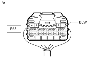
*a Front view of wire harness connector
(to Air Conditioning Amplifier Assembly)
Disconnect the air conditioning amplifier assembly connector.
-
Measure the voltage according to the value(s) in the table below.
Standard Voltage Tester Connection Condition Specified Condition P58-6 (BLW) - Body ground Always 4.75 to 5.25 V Result Proceed to OK NG
NG
REPLACE BLOWER WITH FAN MOTOR SUB-ASSEMBLY Click here
OK
-
-
CHECK AIR CONDITIONING AMPLIFIER ASSEMBLY
-
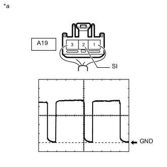
*a Component with harness connected
(Blower with Fan Motor Sub-assembly)
Using the oscilloscope, check for the waveform.
Item Content Terminal No. A19-2 (SI) - Body ground Tool Setting 2 V/DIV., 1 ms./DIV. Vehicle Condition
-
Power switch on (IG)
-
Blower switch: LO
Tech Tips
The waveform varies with the blower speed.
OK Waveform is similar to that shown in the illustration. Result Proceed to OK NG -
OK
REPLACE BLOWER WITH FAN MOTOR SUB-ASSEMBLY Click here
NG
REPLACE AIR CONDITIONING AMPLIFIER ASSEMBLY Click here
-