AIR CONDITIONING SYSTEM, Diagnostic DTC:B1461
| DTC Code | DTC Name |
|---|---|
| B1461 | Emission Gas NOx Sensor Circuit |
DESCRIPTION
The smog ventilation sensor is installed to the front of the cooler condenser assembly to automatically control the air inlet mode (fresh, recirculation/fresh, and recirculation).
This sensor detects NOx in the ambient air and transmits signals to the air conditioning amplifier assembly.
| DTC No. | Detection Item | DTC Detection Condition | Trouble Area | Memory |
|---|---|---|---|---|
| B1461 | Emission Gas NOx Sensor Circuit |
|
|
- |
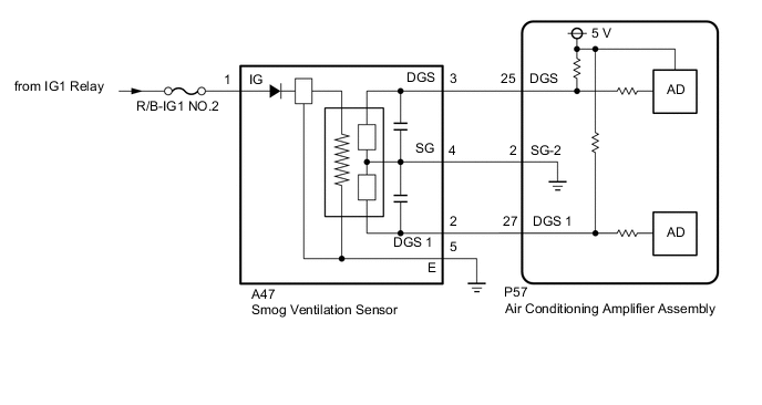
WIRING DIAGRAM
CAUTION / NOTICE / HINT
Note
-
Inspect the fuses for circuits related to this system before performing the following procedure.
-
If DTCs B1418 and B1461 are stored simultaneously, there may be a malfunction in the smog ventilation sensor power source circuit.
PROCEDURE
-
READ VALUE USING GTS (EMISSION GAS NOX SENSOR)
-
Connect the GTS to the DLC3.
-
Turn the power switch on (IG).
-
Turn the GTS on.
-
Allow exhaust gas (NOx) to travel to the sensing portion of the smog ventilation sensor.
-
Enter the following menus: Body Electrical / Air Conditioner / Data List.
-
Read the Data List according to the display on the GTS.
Body Electrical > Air Conditioner > Data ListTester Display Measurement Item Range Normal Condition Diagnostic Note Emission Gas Nox Sensor Emission gas (NOx) Min.: 0
Max.: 255
Smog ventilation sensor value increases as gas amount increases Smog ventilation sensor malfunction
Body Electrical > Air Conditioner > Data ListTester Display Emission Gas Nox Sensor OK The display is as specified in the normal condition column. Result Proceed to OK NG
OK 
REPLACE AIR CONDITIONING AMPLIFIER ASSEMBLY Click here
NG 
-
-
CHECK HARNESS AND CONNECTOR (SMOG VENTILATION SENSOR - BATTERY AND BODY GROUND)
-
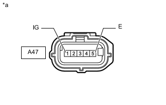
*a Front view of wire harness connector
(to Smog Ventilation Sensor)
Disconnect the smog ventilation sensor connector.
-
Measure the resistance according to the value(s) in the table below.
Standard Resistance Tester Connection Condition Specified Condition A47-5 (E) - Body ground Always Below 1 Ω -
Measure the voltage according to the value(s) in the table below.
Standard Voltage Tester Connection Switch Condition Specified Condition A47-1 (IG) - Body ground Power switch on (IG) 11 to 14 V A47-1 (IG) - Body ground Power switch off Below 1 V Result Proceed to OK NG
NG
REPAIR OR REPLACE HARNESS OR CONNECTOR
OK
-
-
INSPECT SMOG VENTILATION SENSOR
-
Remove the smog ventilation sensor.
-
Inspect the smog ventilation sensor.
Result Proceed to OK NG
NG
REPLACE SMOG VENTILATION SENSOR Click here
OK
-
-
CHECK HARNESS AND CONNECTOR (SMOG VENTILATION SENSOR - AIR CONDITIONING AMPLIFIER ASSEMBLY)
-
Disconnect the A47 Smog ventilation sensor connector.
-
Disconnect the P57 air conditioning amplifier assembly connector.
-
Measure the resistance according to the value(s) in the table below.
Standard Resistance Tester Connection Condition Specified Condition A47-4 (SG) - P57-2 (SG-2) Always Below 1 Ω A47-2 (DGS 1) - P57-27 (DGS 1) Always Below 1 Ω A47-4 (SG) or P57-2 (SG-2) - Other terminals and body ground Always 10 kΩ or higher A47-2 (DGS 1) or P57-27 (DGS 1) - Other terminals and body ground Always 10 kΩ or higher Result Proceed to OK NG
OK
REPLACE AIR CONDITIONING AMPLIFIER ASSEMBLY Click here
NG
REPAIR OR REPLACE HARNESS OR CONNECTOR
-