AIR CONDITIONING SYSTEM, Diagnostic DTC:B1498
| DTC Code | DTC Name |
|---|---|
| B1498 | Communication Malfunction (A/C Inverter Local) |
DESCRIPTION
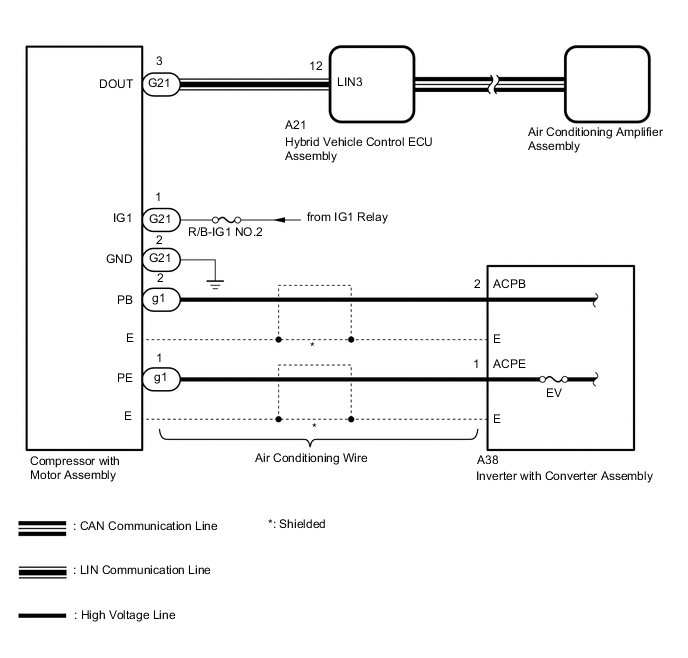
The hybrid vehicle control ECU assembly and compressor with motor assembly communicate via a direct line. Compressor control is stopped and this DTC is stored if communication information is cut off or abnormal information occurs.
This DTC is also detected if high-voltage power supplied from the inverter with converter assembly to the compressor control circuit is shut off.
This DTC will be stored as a history DTC.
| DTC No. | Detection Item | DTC Detection Condition | Trouble Area | Memory |
|---|---|---|---|---|
| B1498 | Communication Malfunction (A/C Inverter Local) |
|
|
Memorized |
WIRING DIAGRAM
CAUTION / NOTICE / HINT
CAUTION:
-
Wear insulated gloves and pull out the service plug grip before inspection as procedures may require disconnecting high-voltage connectors. Carry the removed service plug in your pocket to prevent other technicians from accidentally reconnecting it while you are servicing the vehicle.
-
Do not touch the high-voltage connectors or terminals for 10 minutes after the service plug grip is removed.
Note
-
Inspect the fuses for circuits related to this system before performing the following procedure.
-
After turning the power switch off, waiting time may be required before disconnecting the cable from the negative (-) auxiliary battery terminal. Therefore, make sure to read the disconnecting the cable from the negative (-) auxiliary battery terminal notices before proceeding with work.
-
The hybrid control system and air conditioning system output DTCs separately. Perform troubleshooting for the hybrid control system first if DTCs from these systems are output simultaneously.
-
Depending on the timing of the power supply to the 12 V power supply circuit and high-voltage circuit when the power switch is turned on (READY), an abnormal information signal may be output, causing this DTC to be stored. If the output DTC is a code that was memorized in the past, check the fuses and wire harnesses. If there is no malfunction, clear the DTC.
PROCEDURE
-
CHECK CAN COMMUNICATION SYSTEM
-
Using the GTS, check if the CAN communication system is functioning normally.
Result Result Proceed to CAN communication system DTCs are not output A CAN communication system DTCs are output B
B 
GO TO CAN COMMUNICATION SYSTEM Click here
A 
-
-
CHECK FOR DTC (HYBRID CONTROL SYSTEM)
-
Check if hybrid control system DTCs are output.
Powertrain > Hybrid Control > Trouble CodesResult Result Proceed to DTCs are not output A DTCs are output B
B
GO TO HYBRID CONTROL SYSTEM Click here
A
-
-
CHECK HARNESS AND CONNECTOR (COMPRESSOR WITH MOTOR ASSEMBLY - HYBRID VEHICLE CONTROL ECU ASSEMBLY)
-
Disconnect the G21 compressor with motor assembly connector.
-
Disconnect the A21 hybrid vehicle control ECU assembly connector.
-
Measure the resistance according to the value(s) in the table below.
Standard Resistance Tester Connection Condition Specified Condition G21-3 (DOUT) - A21-12 (LIN3) Always Below 1 Ω G21-3 (DOUT) - A21-12 (LIN3) - Other terminals and body ground Always 10 kΩ or higher Result Proceed to OK NG
NG
REPAIR OR REPLACE HARNESS OR CONNECTOR
OK
-
-
CHECK HARNESS AND CONNECTOR (COMPRESSOR WITH MOTOR ASSEMBLY - BATTERY AND BODY GROUND)
CAUTION:
Do not disconnect the connector on the high-voltage side.
-
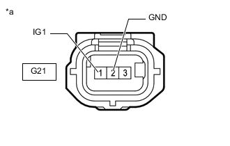
*a Front view of wire harness connector
(to Compressor with Motor Assembly)
Disconnect the compressor with motor assembly connector.
-
Measure the resistance according to the value(s) in the table below.
Standard Resistance Tester Connection Condition Specified Condition G21-2 (GND) - Body ground Always Below 1 Ω -
Measure the voltage according to the value(s) in the table below.
Standard Voltage Tester Connection Switch Condition Specified Condition G21-1 (IG1) - Body ground Power switch on (IG) 11 to 14 V Power switch off Below 1 V Result Proceed to OK NG
NG
REPAIR OR REPLACE HARNESS OR CONNECTOR
OK
-
-
INSPECT EV FUSE
CAUTION:
Be sure to wear insulated gloves.
-
Turn the power switch off.
-
Remove the service plug grip.
CAUTION:
Do not touch the high-voltage connectors or terminals for 10 minutes after the service plug grip is removed.
Note
After removing the service plug grip, turning the power switch on (READY) may cause a malfunction. Do not turn the power switch on (READY) with the service plug grip removed.
-
Remove the connector cover assembly.
Note
Be sure to prevent foreign matter or water from entering the inverter with converter assembly.
-
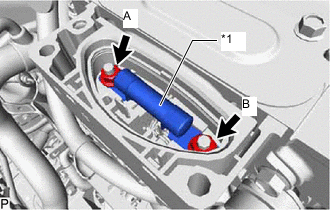
1a EV Fuse Check that bolts A and B are tightened securely.
-
Measure the resistance according to the value(s) in the table below.
Standard Resistance Tester Item
(Tester Connection)
Condition Specified Condition EV fuse
(A - B)
Always Below 1 Ω Result Proceed to OK NG
NG
REPLACE EV FUSE Click here
OK
-
-
CHECK AIR CONDITIONING WIRE (COMPRESSOR WITH MOTOR ASSEMBLY - INVERTER WITH CONVERTER ASSEMBLY)
CAUTION:
Be sure to wear insulated gloves.
-
Disconnect the g1 compresser with motor assembly connector.
-
Disconnect the air conditioning wire from the inverter with converter assembly.
Note
Be sure to prevent foreign matter or water from entering the inverter with converter assembly.
-
Measure the resistance according to the value(s) in the table below.
Standard Resistance Tester Connection Condition Specified Condition A38-1 (ACPE) - g1-1 (PE) Always Below 1 Ω A38-2 (ACPB) - g1-2 (PB) Always Below 1 Ω A38-1 (ACPE) or g1-1 (PE) - Other terminals and body ground Always 10 kΩ or higher A38-2 (ACPB) or g1-2 (PB) - Other terminals and body ground Always 10 kΩ or higher Result Proceed to OK NG
OK
REPLACE COMPRESSOR WITH MOTOR ASSEMBLY Click here
NG
REPLACE AIR CONDITIONING WIRE Click here
-