COMPRESSOR REMOVAL
CAUTION / NOTICE / HINT
The necessary procedures (adjustment, calibration, initialization, or registration) that must be performed after parts are removed, installed, or replaced during the compressor with motor assembly removal/installation are shown below.
| Replaced Part or Performed Procedure | Necessary Procedures | Effect/Inoperative Function when Necessary Procedure not Performed | Link |
|---|---|---|---|
| Disconnect cable from negative auxiliary battery terminal | Memorize steering angle neutral point | LKA/LDA system | |
| Pre-collision system | |||
| Parking assist monitor system | |||
| Steering sensor zero point calibration | Variable gear ratio steering system |
CAUTION:
-
This vehicle has contains high voltage circuits standardized with orange colored wiring and connectors, so follow the instructions in this manual to perform the procedures correctly.
-
If the correct procedures are not followed according to the instructions in this manual, there is a danger of electric shock from the high voltage circuits.
-
Be sure to wear insulating gloves when working on high voltage wiring or components.
-
If work is performed without wearing insulating gloves, there is a danger of electric shock.
Tech Tips
-
Use the same procedure for RHD and LHD vehicles.
-
The procedure listed below is for LHD vehicles.
PROCEDURE
-
REMOVE NO. 1 ENGINE UNDER COVER ASSEMBLY
-
REMOVE NO. 2 ENGINE UNDER COVER ASSEMBLY
-
REMOVE V-BANK COVER SUB-ASSEMBLY
-
RECOVER REFRIGERANT FROM REFRIGERATION SYSTEM
for HFC-134a(R134a):
for HFO-1234yf(R1234yf):
-
CHECK FOR DTC
CAUTION:
-
Confirm that DTC P0AA649 (Hybrid/EV Battery Voltage System Isolation Internal Electronic Failure), P1C7C49 (Hybrid/EV Battery Voltage System Isolation (A/C Area) Internal Electronic Failure), P1C7D49 (Hybrid/EV Battery Voltage System Isolation (Hybrid/EV Battery Area) Internal Electronic Failure), P1C7E49 (Hybrid/EV Battery Voltage System Isolation (Transaxle Area) Internal Electronic Failure) or P1C7F49 (Hybrid/EV Battery Voltage System Isolation (Direct Current Area) Internal Electronic Failure) is not output before removing or installing the HV battery assembly. If this DTC is output, perform troubleshooting for this DTC first.
-
To reduce the risk of electric shock, do not perform troubleshooting before checking for DTCs.
-
-
PRECAUTION
Note
After turning the power switch off, waiting time may be required before disconnecting the cable from the negative (-) auxiliary battery terminal. Therefore, make sure to read the disconnecting the cable from the negative (-) auxiliary battery terminal notices before proceeding with work.
-
REMOVE NO. 2 DECK BOARD
-
DISCONNECT CABLE FROM NEGATIVE AUXILIARY BATTERY TERMINAL
-
REMOVE SERVICE PLUG GRIP
-
CHECK TERMINAL VOLTAGE
-
Remove the connector cover assembly.
-
Check the terminal voltage.
-
Install the connector cover assembly.
-
-
REMOVE RADIATOR SUPPORT TO CROSSMEMBER BRACE SUB-ASSEMBLY LH
-
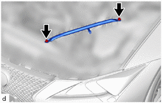
Remove the 2 bolts and radiator support to crossmember brace sub-assembly LH.
-
-
DISCONNECT DISCHARGE HOSE SUB-ASSEMBLY
-
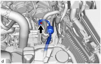
Remove the bolt and disconnect the discharge hose sub-assembly from the compressor with motor assembly.
Note
Do not apply excessive force to the discharge hose sub-assembly.
-
Remove the O-ring from the discharge hose sub-assembly.
Note
Seal the openings of the disconnected parts using vinyl tape to prevent moisture and foreign matter from entering them.
-
-
REMOVE SUCTION HOSE SUB-ASSEMBLY A
-
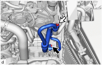

Bolt 
Nut Remove the bolt, nut and suction hose sub-assembly A from the compressor with motor assembly.
Note
Do not apply excessive force to the suction hose sub-assembly A.
-
Remove the 2 O-rings from the suction hose sub-assembly A.
Note
Seal the openings of the disconnected parts using vinyl tape to prevent moisture and foreign matter from entering them.
-
-
REMOVE COMPRESSOR WITH MOTOR ASSEMBLY
-
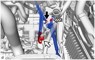
Bolt (A) Connector (A) 
Bolt (B) Disconnect the connector (A).
-
Remove the bolt (A) and disconnect the wiring harness clamp bracket (bolt (A) fastening side).
-
Remove the bolt (B) and disconnect the wiring harness clamp bracket (bolt (B) fastening side).
-
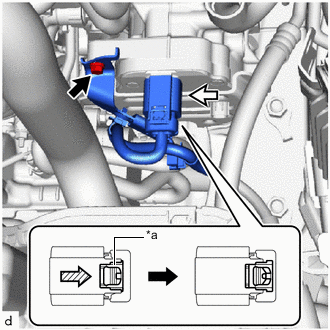
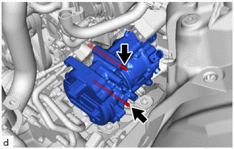
*a Green-colored Lock Bolt (C) Connector (B) Remove the bolt (C) and disconnect the wiring harness clamp bracket (bolt (C) fastening side).
-
Slide the green-colored lock of the connector (B) as shown in the illustration to release it and disconnect the connector.
CAUTION:
Make sure to wear insulating gloves.
Note
Insulate the disconnected terminals and connector with vinyl tape.
-
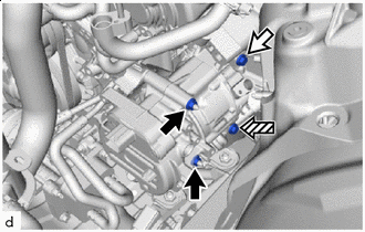
Nut Bolt (D) Bolt (E) Remove the 2 nuts, bolt (D) and bolt (E).
Tech Tips
At this point, bolt (E) interferes with the front frame crossmember sub-assembly. Therefore, it cannot be pulled out from the compressor with motor assembly.
-
Using an E8 "TORX" socket wrench, remove the 2 stud bolts and compressor with motor assembly.
Note
Do not drop or subject the parts to any impact.
-