SEAT BELT WARNING SYSTEM Rear Seat Belt Warning Light Malfunction
DESCRIPTION
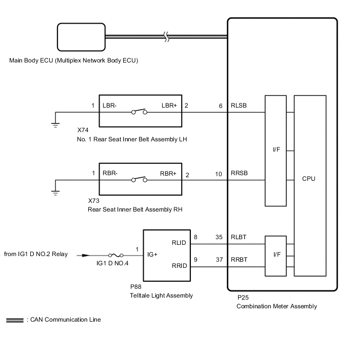
The main body ECU (multiplex network body ECU) detects whether either rear door is open or closed based on the condition of the left and right front door courtesy light switch assemblies and then sends the front door status signal to the combination meter assembly. The combination meter assembly detects the rear seat belt state. The rear seat belt warning lights on the telltail light assembly illuminate or turn off in accordance with the front door state, vehicle speed and rear seat belt state.
WIRING DIAGRAM
CAUTION / NOTICE / HINT
Note
-
The seat belt warning system uses the CAN communication system. First, confirm that there are no malfunctions in the CAN communication system. Refer to the How to Proceed with Troubleshooting procedure.
-
When replacing the combination meter assembly, always replace it with a new one. If a combination meter assembly which was installed to another vehicle is used, the information stored in it will not match the information from the vehicle and a DTC may be stored.
-
Replacing the main body ECU (multiplex network body ECU), refer to Service Bulletin.
PROCEDURE
-
READ VALUE USING GTS (FR DOOR COURTESY SW, FL DOOR COURTESY SW)
-
Connect the GTS to the DLC3.
-
Turn the power switch on (IG).
-
Turn the GTS on.
-
Enter the following menus: Body Electrical / Main Body / Data List.
-
Read the Data List according to the display on the GTS.
Body Electrical > Main Body > Data ListTester Display Measurement Item Range Normal Condition Diagnostic Note FR Door Courtesy SW Front door courtesy light switch assembly RH signal OFF or ON OFF: Front door RH closed
ON: Front door RH open
- FL Door Courtesy SW Front door courtesy light switch assembly LH signal OFF or ON OFF: Front door LH closed
ON: Front door LH open
-
Body Electrical > Main Body > Data ListTester Display FR Door Courtesy SW FL Door Courtesy SW OK The GTS display changes correctly in response to the rear door condition. Result Proceed to OK NG
NG 
GO TO LIGHTING SYSTEM Click here
OK 
-
-
READ VALUE USING GTS (2ND-ROW SEATBELT BUCKLE (R), 2ND-ROW SEATBELT BUCKLE (L))
-
Connect the GTS to the DLC3.
-
Turn the power switch on (IG).
-
Turn the GTS on.
-
Enter the following menus: Body Electrical / Combination Meter / Data List.
-
Read the Data List according to the display on the GTS.
Body Electrical > Combination Meter > Data ListTester Display Measurement Item Range Normal Condition Diagnostic Note 2nd-Row Seatbelt Buckle (R) Rear RH seat belt buckle switch signal ON or OFF ON: Rear RH seat belt fastened
OFF: Rear RH seat belt not fastened
- 2nd-Row Seatbelt Buckle (L) Rear LH seat belt buckle switch signal ON or OFF ON: Rear LH seat belt fastened
OFF: Rear LH seat belt not fastened
-
Body Electrical > Combination Meter > Data ListTester Display 2nd-Row Seatbelt Buckle (R) 2nd-Row Seatbelt Buckle (L) OK ON or OFF is displayed on the GTS according to the rear seat belt condition. Result Proceed to OK NG
NG 
INSPECT REAR SEAT INNER BELT ASSEMBLY Click here
OK
-
-
INSPECT TELLTALE LIGHT ASSEMBLY
-
Remove the telltale light assembly.
-
Inspect he telltale light assembly.
Result Proceed to OK NG
NG
REPLACE TELLTALE LIGHT ASSEMBLY Click here
OK
-
-
CHECK TELLTALE LIGHT ASSEMBLY
-
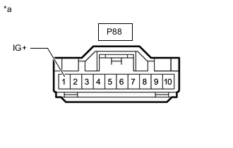
*a Front view of wire harness connector
(to Telltail light assembly connector)
Disconnect the telltale light assembly connector.
-
Measure the voltage according to the value(s) in the table below.
Standard Voltage Teseter Connection Switch Condition Specified Condition P88-1 (IG+) - Body ground Power switch off Below 1 V Power switch on (IG) 11 to 14 V Result Proceed to OK NG
NG
REPAIR OR REPLACE HARNESS OR CONNECTOR
OK
-
-
CHECK HARNESS AND CONNECTOR (TELLTALE LIGHT ASSEMBLY - COMBINATION METER ASSEMBLY)
-
Disconnect the P88 telltale light assembly connector.
-
Disconnect the P25 combination meter assembly connector.
-
Measure the resistance according to the value(s) in the table below.
Standard Resistance Tester Connection Condition Specified Condition P88-8 (RLID) - P25-35 (RLBT) Always Below 1 Ω P88-9 (RRID) - P25-37 (RRBT) Always Below 1 Ω P88-8 (RLID) or P25-35 (RLBT) - Body ground Always 10 kΩ or higher P88-9 (RRID) or P25-37 (RRBT) - Body ground Always 10 kΩ or higher Result Proceed to OK NG
NG
REPAIR OR REPLACE HARNESS OR CONNECTOR
OK
-
-
CHECK COMBINATION METER ASSEMBLY
-
Replace combination meter assembly with a new one.
-
Check the seat belt warning system operation.
OK The seet belt warning function is operated normally. Result Proceed to OK NG
OK
END (COMBINATION METER ASSEMBLY WAS DEFECTIVE)
NG
REPLACE MAIN BODY ECU (MULTIPLEX NETWORK BODY ECU) Click here
-
-
INSPECT REAR SEAT INNER BELT ASSEMBLY
-
for LH:
-
Remove the No. 1 rear seat inner belt assembly LH.
-
Inspect the No. 1 rear seat inner belt assembly LH.
-
-
for RH:
-
Remove the rear seat inner belt assembly RH.
-
Inspect the rear seat inner belt assembly RH.
Result Result Proceed to OK A NG (for LH) B NG (for RH) C -
B
REPLACE NO.1 REAR SEAT INNER BELT ASSEMBLY LH Click here
C
REPLACE REAR SEAT INNER BELT ASSEMBLY RH Click here
A
-
-
CHECK HARNESS AND CONNECTOR (REAR SEAT INNER BELT ASSEMBLY - COMBINATION METER ASSEMBLY AND BODY GROUND)
-
Disconnect the X74 No. 1 rear seat inner belt assembly LH connector.
-
Disconnect the X73 rear seat inner belt assembly RH connector.
-
Disconnec the P25 combination meter assembly connector.
-
Measure the voltage according to the value(s) in the table below.
Standard Voltage for LH Tester Connection Condition Specified Condition X74-2 (LBR+) - P25-6 (RLSB) Always Below 1 Ω X74-1 (LBR-) - Body ground Always Below 1 Ω X74-2 (LBR+) or P25-6 (RLSB) - Body ground Always 10 kΩ or higher for RH Tester Connection Condition Specified Condition X73-2 (RBR+) - P25-10 (RRSB) Always Below 1 Ω X73-1 (RBR-) - Body ground Always Below 1 Ω X73-2 (RBR+) or P25-10 (RRSB) - Body ground Always 10 kΩ or higher Result Proceed to OK NG
OK
REPLACE COMBINATION METER ASSEMBLY Click here
NG
REPAIR OR REPLACE HARNESS OR CONNECTOR
-