CLIMATE CONTROL SEAT SYSTEM Climate Control System does not Operate on Passenger Side
DESCRIPTION
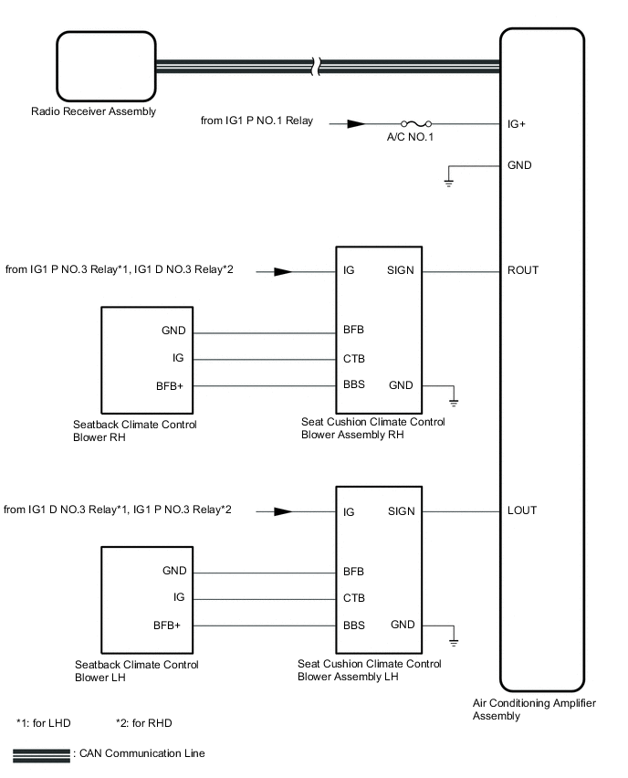
The air conditioning amplifier assembly receives refreshing seat switch position signals when the power switch is on (IG), and then transmits airflow amount signals to each seat climate blower.
WIRING DIAGRAM
CAUTION / NOTICE / HINT
Note
-
Inspect the fuses for circuits related to this system before performing the following procedure.
-
The climate control seat system uses the CAN communication system. Inspect the communication function by following How to Proceed with Troubleshooting. Troubleshoot the climate control seat system after confirming that the communication system is functioning properly.
-
If the auxiliary battery voltage is low, the seat climate control seat system may not operate. When "High Power Consumption Partial Limit On AC/Heater Operation" is displayed on the multi-information display in the combination meter assembly, inspect the auxiliary battery, referring to On-vehicle Inspection for the charging system.
Tech Tips
If the auxiliary battery voltage is low, the climate control seat system may not operate. When "High Power Consumption Partial Limit On AC/Heater Operation" is not displayed on the multi-information display in the combination meter assembly, check the Data List item "Battery Control Count (Body ECU)".
PROCEDURE
-
CHECK CLIMATE CONTROL SEAT OPERATION (FRONT PASSENGER SEAT)
-
Check the climate control seat operation again.
Result Result Proceed to Only seatback climate control blower (front passenger seat) does not operate A Only seat cushion climate control blower assembly (front passenger seat) does not operate B Both climate control blowers do not operate C
B 
REPLACE SEAT CUSHION CLIMETE CONTROL BLOWER ASSEMBLY (FRONT PASSENGER SEAT) Click here
C 
CHECK HARNESS AND CONNECTOR (SEAT CUSHION CLIMATE CONTROL BLOWER ASSEMBLY (FRONT PASSENGER SEAT) - BATTERY AND BODY GROUND) Click here
A 
-
-
CHECK HARNESS AND CONNECTOR (SEAT CUSHION CLIMATE CONTROL BLOWER ASSEMBLY (FRONT PASSENGER SEAT) - SEATBACK CLIMATE CONTROL BLOWER (FRONT PASSENGER SEAT))
-
for LHD:
-
Disconnect the v6 seat cushion climate control blower assembly RH connector.
-
Disconnect the x1 seatback climate control blower RH connector.
-
Measure the resistance according to the value(s) in the table below.
Standard Resistance Tester Connection Condition Specified Condition v6-5 (CTB) - x1-1 (IG) Always Below 1 Ω v6-5 (CTB) or x1-1 (IG) - Other terminals and body ground Always 10 kΩ or higher v6-6 (BBS) - x1-3 (BFB+) Always Below 1 Ω v6-6 (BBS) or x1-3 (BFB+) - Other terminals and body ground Always 10 kΩ or higher v6-4 (BFB) - x1-4 (GND) Always Below 1 Ω v6-4 (BFB) or x1-4 (GND) - Other terminals and body ground Always 10 kΩ or higher
-
-
for RHD:
-
Disconnect the w6 seat cushion climate control blower assembly LH connector.
-
Disconnect the y1 seatback climate control blower LH connector.
-
Measure the resistance according to the value(s) in the table below.
Standard Resistance Tester Connection Condition Specified Condition w6-5 (CTB) - y1-1 (IG) Always Below 1 Ω w6-5 (CTB) or y1-1 (IG) - Other terminals and body ground Always 10 kΩ or higher w6-6 (BBS) - y1-3 (BFB+) Always Below 1 Ω w6-6 (BBS) or y1-3 (BFB+) - Other terminals and body ground Always 10 kΩ or higher w6-4 (BFB) - y1-4 (GND) Always Below 1 Ω w6-4 (BFB) or y1-4 (GND) - Other terminals and body ground Always 10 kΩ or higher
Result Proceed to OK NG -
NG
REPAIR OR REPLACE HARNESS OR CONNECTOR
OK
-
-
REPLACE SEATBACK CLIMATE CONTROL BLOWER (FRONT PASSENGER SEAT)
-
Temporarily replace the seatback climate control blower (front passenger seat) with a new or known good one.
Result Proceed to NEXT
NEXT
-
-
CHECK CLIMATE CONTROL SEAT OPERATION
-
Check the climate control operation again.
OK The climate control seat operates normally. Result Proceed to OK NG
OK
END (SEATBACK CLIMATE CONTROL BLOWER RH WAS DEFECTIVE)
NG
REPLACE SEAT CUSHION CLIMATE CONTROL BLOWER ASSEMBLY (FRONT PASSENGER SEAT) Click here
-
-
CHECK HARNESS AND CONNECTOR (SEAT CUSHION CLIMATE CONTROL BLOWER ASSEMBLY (FRONT PASSENGER SEAT) - BATTERY AND BODY GROUND)
-
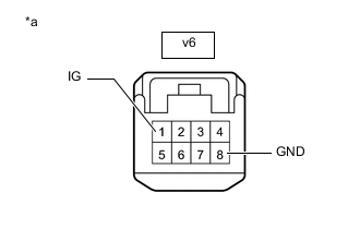
*a Front view of wire harness connector
(to Seat Cushion Climate Control Blower Assembly RH)
for LHD:
-
Disconnect the seat cushion climate control blower assembly RH connector.
-
Measure the resistance according to the value(s) in the table below.
Standard Resistance Tester Connection Condition Specified Condition v6-8 (GND) - Body ground Always Below 1 Ω -
Measure the voltage according to the value(s) in the table below.
Standard Voltage Tester Connection Switch Condition Specified Condition v6-1 (IG) - Body ground Power switch on (IG) 11 to 14 V Power switch off Below 1 V
-
-
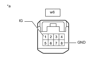
*a Front view of wire harness connector
(to Seat Cushion Climate Control Blower Assembly LH)
for RHD:
-
Disconnect the seat cushion climate control blower assembly LH connector.
-
Measure the resistance according to the value(s) in the table below.
Standard Resistance Tester Connection Condition Specified Condition w6-8 (GND) - Body ground Always Below 1 Ω -
Measure the voltage according to the value(s) in the table below.
Standard Voltage Tester Connection Switch Condition Specified Condition w6-1 (IG) - Body ground Power switch on (IG) 11 to 14 V Power switch off Below 1 V
Result Proceed to OK NG -
NG
REPAIR OR REPLACE HARNESS OR CONNECTOR
OK
-
-
CHECK HARNESS AND CONNECTOR (AIR CONDITIONING AMPLIFIER ASSEMBLY - SEAT CUSHION CLIMATE CONTROL BLOWER ASSEMBLY (FRONT PASSENGER SEAT))
-
for LHD:
-
Disconnect the P58 air conditioning amplifier assembly connector.
-
Disconnect the v6 seat cushion climate control blower assembly RH connector.
-
Measure the resistance according to the value(s) in the table below.
Standard Resistance Tester Connection Condition Specified Condition P58-23 (ROUT) - v6-7 (SIGN) Always Below 1 Ω P58-23 (ROUT) or v6-7 (SIGN) - Other terminals and body ground Always 10 kΩ or higher
-
-
for RHD:
-
Disconnect the P58 air conditioning amplifier assembly connector.
-
Disconnect the w6 seat cushion climate control blower assembly LH
-
Measure the resistance according to the value(s) in the table below.
Standard Resistance Tester Connection Condition Specified Condition P58-24 (LOUT) - w6-7 (SIGN) Always Below 1 Ω P58-24 (LOUT) or w6-7 (SIGN) - Other terminals and body ground Always 10 kΩ or higher
Result Proceed to OK NG -
NG
REPAIR OR REPLACE HARNESS OR CONNECTOR
OK
-
-
CHECK AIR CONDITIONING AMPLIFIER ASSEMBLY
-
Check for pulses according to the value(s) in the table below.
-

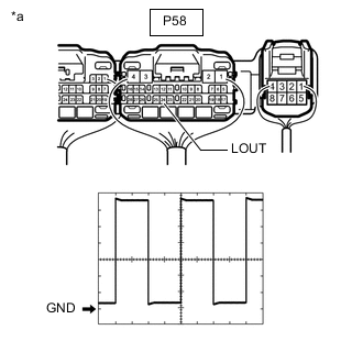
*a Component with harness connected
(Air Conditioning Amplifier Assembly)
for LHD:
Measurement Condition Item Content Tester Connection P58-23 (ROUT) - Body ground Tool Setting 1 V/DIV., 1 ms/DIV. Vehicle Condition
-
Power switch on (IG)
-
Ventilation volume switch RH on
-
-
*a Component with harness connected
(Air Conditioning Amplifier Assembly)
for RHD:
Measurement Condition Item Content Tester Connection P58-24 (LOUT) - Body ground Tool Setting 1 V/DIV., 1 ms/DIV. Vehicle Condition
-
Power switch on (IG)
-
Ventilation volume switch RH on
-
OK Waveform is similar to that shown in the illustration. Result Proceed to OK NG -
OK
REPLACE SEAT CUSHION CLIMATE CONTROL BLOWER ASSEMBLY (FRONT PASSENGER SEAT) Click here
NG
REPLACE AIR CONDITIONING AMPLIFIER ASSEMBLY Click here
-