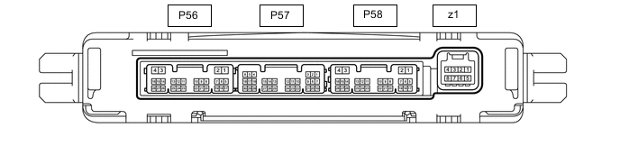
CLIMATE CONTROL SEAT SYSTEM TERMINALS OF ECU
-
CHECK AIR CONDITIONING AMPLIFIER ASSEMBLY
-
Disconnect the P58 air conditioning amplifier assembly connector.
-
Measure the voltage and resistance according to the value(s) in the table below.
Terminal No. (Symbol) Wiring Color Terminal Description Condition Specified Condition P58-2 (IG+) - Body ground R - Body ground IG power supply Power switch on (IG) 11 to 14 V Power switch off Below 1 V P58-4 (GND) - Body ground W-B - Body ground Ground Always Below 1 Ω -
Reconnect the P58 air conditioning amplifier assembly connector.
-
Check for pulses according to the value(s) in the table below.
Terminal No. (Symbol) Wiring Color Terminal Description Condition Specified Condition P58-23 (ROUT) - Body ground BE - Body ground Climate control blower control signal
-
Power switch on (IG)
-
Ventilation volume switch RH on
Pulse generation
(See waveform)
P58-24 (LOUT) - Body ground R - Body ground Climate control blower control signal
-
Power switch on (IG)
-
Ventilation volume switch LH on
Pulse generation
(See waveform)
-
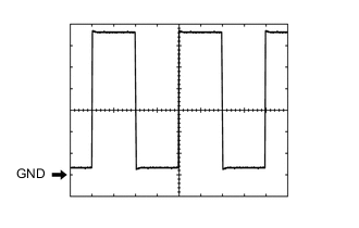
Waveform (Reference):
Measurement Condition Item Content Tester Connection
-
P58-23 (ROUT) - Body ground
-
P58-24 (LOUT) - Body ground
Tool Setting 1 V/DIV., 1 ms/DIV. Vehicle Condition
-
Power switch on (IG)
-
Ventilation volume switch on
-
-
-
-
CHECK RADIO RECEIVER ASSEMBLY