SEAT HEATER SYSTEM Seat Heater for Front Right Seat does not Operate
DESCRIPTION
When the seat heater switch is operated, the air conditioning amplifier assembly receives the signal via CAN communication line. The air conditioning amplifier assembly receives the signal and operates the front seat heater.
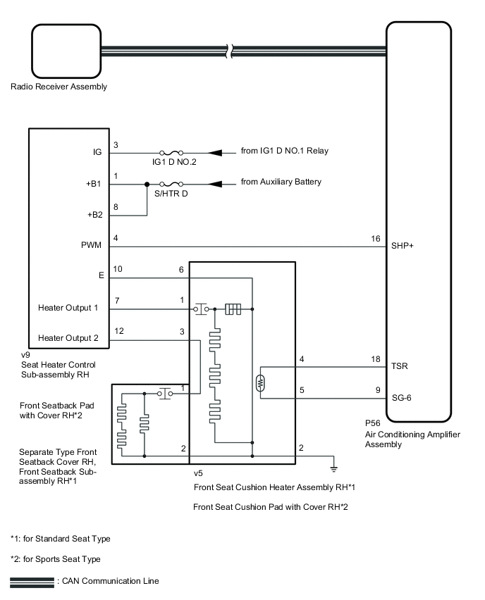
WIRING DIAGRAM
Figure 1. for LHD:
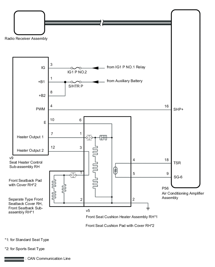
Figure 2. for RHD:
CAUTION / NOTICE / HINT
Note
-
If the auxiliary battery voltage is low, the seat heater system may not operate. When "High Power Consumption Partial Limit On AC/Heater Operation" is displayed on the multi-information display in the combination meter assembly, inspect the auxiliary battery, referring to On-vehicle Inspection for the charging system.
-
Inspect the fuses for circuits related to this system before performing the following procedure.
Tech Tips
If the auxiliary battery voltage is low, the seat heater system may not operate. When "High Power Consumption Partial Limit On AC/Heater Operation" is not displayed on the multi-information display in the combination meter assembly, check the Data List item "Battery Control Count (Body ECU)".
PROCEDURE
-
CLEAR DTC
-
Clear the DTCs.
Body Electrical > Air Conditioner > Clear DTCsResult Proceed to NEXT
NEXT 
-
-
CHECK FOR DTC
-
Check for DTCs.
Body Electrical > Air Conditioner > Trouble CodesOK DTC B14C0 is not output. Result Proceed to OK NG
NG 
GO TO DIAGNOSTIC TROUBLE CODE CHART Click here
OK
-
-
CHECK HARNESS AND CONNECTOR (SEAT HEATER CONTROL SUB-ASSEMBLY RH - BATTERY)
-
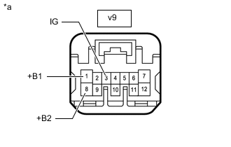
*a Front view of wire harness connector
(to Seat Heater Control Sub-assembly RH)
Disconnect the seat heater control sub-assembly RH connector.
-
Measure the voltage according to the value(s) in the table below.
Standard Voltage Tester Connection Switch Condition Specified Condition v9-3 (IG) - Body ground Power switch on (IG) 11 to 14 V Power switch off Below 1 V v9-1 (+B1) - Body ground Power switch off 11 to 14 V v9-8 (+B2) - Body ground Power switch off 11 to 14 V Result Result Proceed to OK (for Standard Seat Type) A OK (for Sports Seat Type) B NG C
B 
INSPECT FRONT SEAT CUSHION PAD WITH COVER RH Click here
C
REPAIR OR REPLACE HARNESS OR CONNECTOR
A
-
-
INSPECT FRONT SEAT CUSHION HEATER ASSEMBLY RH
-
Remove the front seat cushion heater assembly RH.
-
Inspect the front seat cushion heater assembly RH.
Result Proceed to OK NG
NG
REPLACE FRONT SEAT CUSHION HEATER ASSEMBLY RH Click here
OK
-
-
INSPECT FRONT SEATBACK SUB-ASSEMBLY RH
-
Remove the front seatback sub-assembly RH.
-
Inspect the front seatback sub-assembly RH.
Result Proceed to OK NG
NG
REPLACE FRONT SEAT BACK SUB-ASSEMBLY RH Click here
OK
-
-
INSPECT SEPARATE TYPE FRONT SEATBACK COVER RH
-
Remove the separate type front seatback cover RH.
-
Inspect the separate type front seatback cover RH.
Result Proceed to OK NG
NG
REPLACE SEPARATE TYPE FRONT SEATBACK COVER RH Click here
OK
-
-
CHECK HARNESS AND CONNECTOR (FRONT SEAT CUSHION HEATER ASSEMBLY RH - SEAT HEATER CONTROL SUB-ASSEMBLY RH AND BODY GROUND)
-
Disconnect the v5 front seat cushion heater assembly RH connector.
-
Disconnect the v9 seat heater control sub-assembly RH connector.
-
Measure the resistance according to the value(s) in the table below.
Standard Resistance Tester Connection Condition Specified Condition v5-6 - v9-10 (E) Always Below 1 Ω v5-6 or v9-10 (E) - Other terminals and body ground Always 10 kΩ or higher v5-1 - v9-7 (Heater Output 1) Always Below 1 Ω v5-1 or v9-7 (Heater Output 1) - Other terminals and body ground Always 10 kΩ or higher v5-3 - v9-12 (Heater Output 2) Always Below 1 Ω v5-3 or v9-12 (Heater Output 2) - Other terminals and body ground Always 10 kΩ or higher v5-2 - Body ground Always Below 1 Ω Result Proceed to OK NG
NG
REPAIR OR REPLACE HARNESS OR CONNECTOR
OK
-
-
CHECK HARNESS AND CONNECTOR (FRONT SEAT CUSHION HEATER ASSEMBLY RH - AIR CONDITIONING AMPLIFIER ASSEMBLY)
-
Disconnect the v9 front seat cushion heater assembly RH connector.
-
Disconnect the P56 air conditioning amplifier assembly connector.
-
Measure the resistance according to the value(s) in the table below.
Standard Resistance Tester Connection Condition Specified Condition v9-4 - P56-18 (TSR) Always Below 1 Ω v9-4 or P56-18 (TSR) - Other terminals and body ground Always 10 kΩ or higher v9-5 - P56-9 (SG-6) Always Below 1 Ω v9-5 or P56-9 (SG-6) - Other terminals and body ground Always 10 kΩ or higher Result Proceed to OK NG
NG
REPAIR OR REPLACE HARNESS OR CONNECTOR
OK
-
-
CHECK HARNESS AND CONNECTOR (SEAT HEATER CONTROL SUB-ASSEMBLY RH - AIR CONDITIONING AMPLIFIER ASSEMBLY)
-
Disconnect the v9 seat heater control sub-assembly RH connector.
-
Disconnect the P56 air conditioning amplifier assembly connector.
-
Measure the resistance according to the value(s) in the table below.
Standard Resistance Tester Connection Condition Specified Condition v9-4 (PWM) - P56-16 (SHP+) Always Below 1 Ω v9-4 (PWM) or P56-16 (SHP+) - Other terminals and body ground Always 10 kΩ or higher Result Proceed to OK NG
NG
REPAIR OR REPLACE HARNESS OR CONNECTOR
OK
-
-
REPLACE SEAT HEATER CONTROL SUB-ASSEMBLY RH
-
Temporarily replace the seat heater control sub-assembly RH with a new or known good one.
Result Proceed to NEXT
NEXT
-
-
CHECK SEAT HEATER OPERATION
-
Check the seat heater.
OK The seat heater operates normally. Result Proceed to OK NG
OK
END (SEAT HEATER CONTROL SUB-ASSEMBLY RH WAS DEFECTIVE)
NG
REPLACE AIR CONDITIONING AMPLIFIER ASSEMBLY Click here
-
-
INSPECT FRONT SEAT CUSHION PAD WITH COVER RH
-
Remove the front seat cushion pad with cover RH.
-
Inspect the front seat cushion pad with cover RH.
Result Proceed to OK NG
NG
REPLACE FRONT SEAT CUSHION PAD WITH COVER RH Click here
OK
-
-
INSPECT FRONT SEATBACK PAD WITH COVER RH
-
Remove the front seatback pad with cover RH.
-
Inspect the front seatback pad with cover RH.
Result Proceed to OK NG
NG
REPLACE FRONT SEATBACK PAD WITH COVER RH Click here
OK
-
-
CHECK HARNESS AND CONNECTOR (FRONT SEAT CUSHION PAD WITH COVER RH - SEAT HEATER CONTROL SUB-ASSEMBLY RH AND BODY GROUND)
-
Disconnect the v5 front seat cushion pad with cover RH connector.
-
Disconnect the v9 seat heater control sub-assembly RH connector.
-
Measure the resistance according to the value(s) in the table below.
Standard Resistance Tester Connection Condition Specified Condition v5-6 - v9-10 (E) Always Below 1 Ω v5-6 or v9-10 (E) - Other terminals and body ground Always 10 kΩ or higher v5-1 - v9-7 (Heater Output 1) Always Below 1 Ω v5-1 or v9-7 (Heater Output 1) - Other terminals and body ground Always 10 kΩ or higher v5-3 - v9-12 (Heater Output 2) Always Below 1 Ω v5-3 or v9-12 (Heater Output 2) - Other terminals and body ground Always 10 kΩ or higher v5-2 - Body ground Always Below 1 Ω Result Proceed to OK NG
NG
REPAIR OR REPLACE HARNESS OR CONNECTOR
OK
-
-
CHECK HARNESS AND CONNECTOR (FRONT SEAT CUSHION PAD WITH COVER RH - AIR CONDITIONING AMPLIFIER ASSEMBLY)
-
Disconnect the v9 front seat cushion pad with cover RH connector.
-
Disconnect the P56 air conditioning amplifier assembly connector.
-
Measure the resistance according to the value(s) in the table below.
Standard Resistance Tester Connection Condition Specified Condition v9-4 - P56-18 (TSR) Always Below 1 Ω v9-4 or P56-18 (TSR) - Other terminals and body ground Always 10 kΩ or higher v9-5 - P56-9 (SG-6) Always Below 1 Ω v9-5 or P56-9 (SG-6) - Other terminals and body ground Always 10 kΩ or higher Result Proceed to OK NG
OK
GO TO STEP 9 Click here
NG
REPAIR OR REPLACE HARNESS OR CONNECTOR
-