FRONT POWER SEAT CONTROL SYSTEM One-touch Walk-in Function does not Operate
DESCRIPTION
When the reclining remote control lever sub-assembly is operated and the front seatback frame sub-assembly is folded forward, each limit switch is turned on and sends a signal to the position control ECU assembly according to the condition of the front seatback frame sub-assembly.
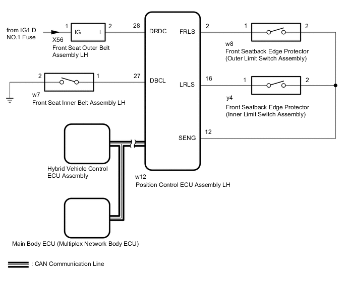
WIRING DIAGRAM
-
for Driver Seat
Figure 1. for LHD:

Figure 2. for RHD:

-
for Front Passenger Seat
Figure 3. for LHD:

Figure 4. for RHD:
CAUTION / NOTICE / HINT
Note
-
The front power seat control system uses the CAN communication system. First, confirm that there are no malfunctions in the CAN communication system. Refer to How to Proceed with Troubleshooting.
-
Before replacing the main body ECU (multiplex network body ECU), refer to SERVICE BULLETIN.
-
Initializing the position control ECU assembly will clear the seat position memory.
Tech Tips
-
Make sure to initialize the position control ECU assembly after replacing the seat assembly or any related parts (including removal and installation).
-
Before initializing the seat ECU, make sure that the D/C CUT fuse is normal.
-
When any of the following conditions are met, the seat position Information in the position control ECU assembly will be cleared.
-
The power switch is turned off with any of the seat switches being operated and the D/C CUT fuse removed.
-
The power switch is turned off within 1 second of any of the seat switches being operated with the D/C CUT fuse removed.
PROCEDURE
-
CHECK SEAT BELT TENSION REDUCER SYSTEM
-
Check the seat belt tension reducer system.
OK Seat belt tension reducer system is normal. Result Proceed to OK NG
NG 
GO TO SEAT BELT TENSION REDUCER SYSTEM Click here
OK 
-
-
CHECK FOR DTC (ELECTRONIC SHIFT LEVER SYSTEM)
-
Perform "DTC Output Confirmation Operation" procedure.
-
Check for DTCs.
Powertrain > Hybrid Control > Trouble CodesOK DTS is not output. Result Proceed to OK NG
NG
GO TO ELECTRONIC SHIFT LEVER SYSTEM Click here
OK
-
-
CHECK FRONT POWER SEAT OPERATION
-
Check that each function of the power seat operates normally by using the front power seat switch.
Result Result Proceed to Driver power seat functions do not operate A Front passenger power seat functions do not operate B
B 
READ VALUE USING GTS (SHIFT P POSITION STATE) Click here
A
-
-
READ VALUE USING GTS (SHIFT SW POSITION)
-
Connect the GTS to the DLC3.
-
Turn the power switch on (IG).
-
Turn the GTS on.
-
Enter the following menus: Body Electrical / Driver Seat / Data List.
-
Read the Data List according to the display on the GTS.
Body Electrical > Driver Seat > Data ListTester Display Measurement Item Range Normal Condition Diagnostic Note Shift SW Position Park state signal Shift P or Shift Other Shift P: Shift lever in P
Shift Other: Shift lever in a position other than P
-
Body Electrical > Driver Seat > Data ListTester Display Shift SW Position OK The GTS display changes correctly in response to the shift lever position. Result Proceed to OK NG
NG
REPLACE POSITION CONTROL ECU ASSEMBLY (FOR DRIVER SEAT) Click here
OK
-
-
READ VALUE USING GTS (OPERATION LEVER STATE AND SLIDE FRONT OPERATION PERMITTED)
-
Connect the GTS to the DLC3.
-
Turn the power switch on (IG).
-
Turn the GTS on.
-
Enter the following menus: Body Electrical / Driver Seat / Data List.
-
Read the Data List according to the display on the GTS.
Body Electrical > Driver Seat > Data ListTester Display Measurement Item Range Normal Condition Diagnostic Note Operation Lever State Reclining remote control lever sub-assembly state Lock or Unlock Lock: Reclining remote control lever sub-assembly locked
Unlock: Reclining remote control lever sub-assembly unlocked
- Slide Front Operation Permitted Forward operation permission state NO or YES NO: Not permitted
YES: Permitted
-
Body Electrical > Driver Seat > Data ListTester Display Operation Lever State Slide Front Operation Permitted Result Result Proceed to The value of each Data List item change accordingly. A The value of the Data List item "Operation Lever State"not change according to the operation of the reclining remote control lever sub-assembly. B The value of the Data List item "Slide Front Operation Permitted" does not change according to the forward operation permission state. C The value of each Data List item does not change. D
A
USE SIMULATION METHOD TO CHECK Click here
C
INSPECT FRONT SEAT BACK EDGE PROTECTOR (OUTER LIMIT SWITCH ASSEMBLY) Click here
D
CHECK HARNESS AND CONNECTOR (POSITION CONTROL ECU ASSEMBLY (FOR DRIVER SEAT) - FRONT SEATBACK EDGE PROTECTOR (OUTER LIMIT SWITCH ASSEMBLY)) Click here
B
-
-
INSPECT FRONT SEATBACK EDGE PROTECTOR (INNER LIMIT SWITCH ASSEMBLY)
-
Remove the front seatback edge protector (inner limit switch assembly).
-
Inspect the front seatback edge protector (inner limit switch assembly).
Result Proceed to OK NG
NG
REPLACE FRONT SEATBACK EDGE PROTECTOR (INNER LIMIT SWITCH ASSEMBLY) Click here
OK
-
-
CHECK HARNESS AND CONNECTOR (POSITION CONTROL ECU ASSEMBLY (FOR DRIVE SEAT) - FRONT SEATBACK EDGE PROTECTOR (INNER LIMIT SWITCH ASSEMBLY))
-
for LHD:
-
Disconnect the w12 position control ECU assembly LH connector.
-
Disconnect the w8 front seatback edge protector (inner limit switch assembly) connector.
-
Measure the resistance according to the value(s) in the table below.
Standard Resistance Tester Connection Condition Specified Condition w12-2 (FRLS) - w8-1 Always Below 1 Ω w12-2 (FRLS) or w8-1 - Other terminals and body ground Always 10 kΩ or higher w12-12 (SENG) - w8-2 Always Below 1 Ω
-
-
for RHD:
-
Disconnect the v12 position control ECU assembly RH connector.
-
Disconnect the v8 front seatback edge protector (inner limit switch assembly) connector.
-
Measure the resistance according to the value(s) in the table below.
Standard Resistance Tester Connection Condition Specified Condition v12-2 (FRLS) - v8-1 Always Below 1 Ω v12-2 (FRLS) or v8-1 - Other terminals and body ground Always 10 kΩ or higher v12-12 (SENG) - v8-2 Always Below 1 Ω
Result Proceed to OK NG -
OK
REPLACE POSITION CONTROL ECU ASSEMBLY FOR DRIVER SEAT Click here
NG
REPAIR OR REPLACE HARNESS OR CONNECTOR
-
-
INSPECT FRONT SEAT BACK EDGE PROTECTOR (OUTER LIMIT SWITCH ASSEMBLY)
-
Remove the front seatback edge protector (outer limit switch assembly).
-
Inspect the front seatback edge protector (outer limit switch assembly).
Result Proceed to OK NG
NG
REPLACE FRONT SEATBACK EDGE PROTECTOR (OUTER LIMIT SWITCH ASSEMBLY) Click here
OK
-
-
CHECK HARNESS AND CONNECTOR (POSITION CONTROL ECU ASSEMBLY (FOR DRIVER SEAT) - FRONT SEATBACK EDGE PROTECTOR (OUTER LIMIT SWITCH ASSEMBLY))
-
for LHD:
-
Disconnect the w12 position control ECU assembly LH connector.
-
Disconnect the y4 front seatback edge protector (outer limit switch assembly) connector.
-
Measure the resistance according to the value(s) in the table below.
Standard Resistance Tester Connection Condition Specified Condition w12-16 (LRLS) - y4-1 Always Below 1 Ω w12-16 (LRLS) or y4-1 - Other terminals and body ground Always 10 kΩ or higher w12-12 (SENG) - y4-2 Always Below 1 Ω
-
-
for RHD:
-
Disconnect the v12 position control ECU assembly RH connector.
-
Disconnect the x4 front seatback edge protector (outer limit switch assembly) connector.
-
Measure the resistance according to the value(s) in the table below.
Standard Resistance Tester Connection Condition Specified Condition v12-16 (LRLS) - x4-1 Always Below 1 Ω v12-16 (LRLS) or x4-1 - Other terminals and body ground Always 10 kΩ or higher v12-12 (SENG) - x4-2 Always Below 1 Ω
Result Proceed to OK NG -
OK
REPLACE POSITION CONTROL ECU ASSEMBLY FOR DRIVER SEAT Click here
NG
REPAIR OR REPLACE HARNESS OR CONNECTOR
-
-
CHECK HARNESS AND CONNECTOR (POSITION CONTROL ECU ASSEMBLY (FOR DRIVER SEAT) - FRONT SEATBACK EDGE PROTECTOR (OUTER LIMIT SWITCH ASSEMBLY))
-
for LHD:
-
Disconnect the w12 position control ECU assembly LH connector.
-
Disconnect the y4 front seatback edge protector (outer limit switch assembly) connector.
-
Measure the resistance according to the value(s) in the table below.
Standard Resistance Tester Connection Condition Specified Condition w12-12 (SENG) - y4-2 Always Below 1 Ω
-
-
for RHD:
-
Disconnect the v12 position control ECU assembly RH connector.
-
Disconnect the x4 front seatback edge protector (outer limit switch assembly) connector.
-
Measure the resistance according to the value(s) in the table below.
Standard Resistance Tester Connection Condition Specified Condition v12-12 (SENG) - x4-2 Always Below 1 Ω
Result Proceed to OK NG -
OK
REPLACE POSITION CONTROL ECU ASSEMBLY (FOR DRIVER SEAT) Click here
NG
REPAIR OR REPLACE HARNESS OR CONNECTOR
-
-
READ VALUE USING GTS (SHIFT P POSITION STATE)
-
Connect the Techstream to the DLC3.
-
Turn the power switch on (IG).
-
Turn the Techstream on.
-
Enter the following menus: Body Electrical / Passenger Seat / Data List.
-
Read the Data List according to the display on the Techstream.
Body Electrical > Passenger Seat > Data ListTester Display Measurement Item Range Normal Condition Diagnostic Note Shift SW Position Park state signal Shift P or Shift Other Shift P: Shift lever in P
Shift Other: Shift lever in a position other than P
-
Body Electrical > Passenger Seat > Data ListTester Display Shift SW Position OK The Techstream display changes correctly in response to the shift lever position. Result Proceed to OK NG
NG
REPLACE POSITION CONTROL ECU ASSEMBLY (FOR PASSENGER SEAT) Click here
OK
-
-
READ VALUE USING TECHSTREAM (OPERATION LEVER STATE AND SLIDE FRONT OPERATION PERMITTED)
-
Connect the GTS to the DLC3.
-
Turn the power switch on (IG).
-
Turn the GTS on.
-
Enter the following menus: Body Electrical / Passenger Seat / Data List.
-
Read the Data List according to the display on the GTS.
Body Electrical > Passenger Seat > Data ListTester Display Measurement Item Range Normal Condition Diagnostic Note Operation Lever State Reclining remote control lever sub-assembly state Lock or Unlock Lock: Reclining remote control lever sub-assembly locked
Unlock: Reclining remote control lever sub-assembly unlocked
- Slide Front Operation Permitted Forward operation permission state NO or YES NO: Not permitted
YES: Permitted
-
Body Electrical > Passenger Seat > Data ListTester Display Operation Lever State Slide Front Operation Permitted Result Result Proceed to The value of each Data List item change accordingly. A The value of the Data List item "Operation Lever State" does not change according to the operation of the reclining remote control lever sub-assembly. B The value of the Data List item "Slide Front Operation Permitted" does not change according to the forward operation permission state. C The value of each Data List item does not change. D
A
USE SIMULATION METHOD TO CHECK Click here
C
INSPECT FRONT SEAT BACK EDGE PROTECTOR (OUTER LIMIT SWITCH ASSEMBLY) Click here
D
CHECK HARNESS AND CONNECTOR (POSITION CONTROL ECU ASSEMBLY (FOR PASSENGER SEAT) - FRONT SEATBACK EDGE PROTECTOR (OUTER LIMIT SWITCH ASSEMBLY)) Click here
B
-
-
INSPECT FRONT SEATBACK EDGE PROTECTOR (INNER LIMIT SWITCH ASSEMBLY)
-
Remove the front seatback edge protector (inner limit switch assembly).
-
Inspect the front seatback edge protector (inner limit switch assembly).
Result Proceed to OK NG
NG
REPLACE FRONT SEATBACK EDGE PROTECTOR (INNER LIMIT SWITCH ASSEMBLY) Click here
OK
-
-
CHECK HARNESS AND CONNECTOR (POSITION CONTROL ECU ASSEMBLY (FOR PASSENGER SEAT) - FRONT SEATBACK EDGE PROTECTOR (INNER LIMIT SWITCH ASSEMBLY))
-
for LHD:
-
Disconnect the v12 position control ECU assembly RH connector.
-
Disconnect the v8 front seatback edge protector (inner limit switch assembly) connector.
-
Measure the resistance according to the value(s) in the table below.
Standard Resistance Tester Connection Condition Specified Condition v12-2 (FRLS) - v8-1 Always Below 1 Ω v12-2 (FRLS) or v8-1 - Other terminals and body ground Always 10 kΩ or higher v12-12 (SENG) - v8-2 Always Below 1 Ω
-
-
for RHD:
-
Disconnect the w12 position control ECU assembly LH connector.
-
Disconnect the w8 front seatback edge protector (inner limit switch assembly) connector.
-
Measure the resistance according to the value(s) in the table below.
Standard Resistance Tester Connection Condition Specified Condition w12-2 (FRLS) - w8-1 Always Below 1 Ω w12-2 (FRLS) or w8-1 - Other terminals and body ground Always 10 kΩ or higher w12-12 (SENG) - w8-2 Always Below 1 Ω
Result Proceed to OK NG -
OK
REPLACE POSITION CONTROL ECU ASSEMBLY (FOR PASSENGER SEAT) Click here
NG
REPAIR OR REPLACE HARNESS OR CONNECTOR
-
-
INSPECT FRONT SEAT BACK EDGE PROTECTOR (OUTER LIMIT SWITCH ASSEMBLY)
-
Remove the front seatback edge protector (outer limit switch assembly).
-
Inspect the front seatback edge protector (outer limit switch assembly).
Result Proceed to OK NG
NG
REPLACE FRONT SEATBACK EDGE PROTECTOR (OUTER LIMIT SWITCH ASSEMBLY) Click here
OK
-
-
CHECK HARNESS AND CONNECTOR (POSITION CONTROL ECU ASSEMBLY (FOR PASSENGER SEAT) - FRONT SEATBACK EDGE PROTECTOR (OUTER LIMIT SWITCH ASSEMBLY))
-
for LHD:
-
Disconnect the v12 position control ECU assembly RH connector.
-
Disconnect the x4 front seatback edge protector (outer limit switch assembly) connector.
-
Measure the resistance according to the value(s) in the table below.
Standard Resistance Tester Connection Condition Specified Condition v12-16 (LRLS) - x4-1 Always Below 1 Ω v12-16 (LRLS) or x4-1 - Other terminals and body ground Always 10 kΩ or higher v12-12 (SENG) - x4-2 Always Below 1 Ω
-
-
for RHD:
-
Disconnect the w12 position control ECU assembly LH connector.
-
Disconnect the y4 front seatback edge protector (outer limit switch assembly) connector.
-
Measure the resistance according to the value(s) in the table below.
Standard Resistance Tester Connection Condition Specified Condition w12-16 (LRLS) - y4-1 Always Below 1 Ω w12-16 (LRLS) or y4-1 - Other terminals and body ground Always 10 kΩ or higher w12-12 (SENG) - y4-2 Always Below 1 Ω
Result Proceed to OK NG -
OK
REPLACE POSITION CONTROL ECU ASSEMBLY (FOR PASSENGER SEAT) Click here
NG
REPAIR OR REPLACE HARNESS OR CONNECTOR
-
-
CHECK HARNESS AND CONNECTOR (POSITION CONTROL ECU ASSEMBLY (FOR PASSENGER SEAT) - FRONT SEATBACK EDGE PROTECTOR (OUTER LIMIT SWITCH ASSEMBLY))
-
for LHD:
-
Disconnect the v12 position control ECU assembly RH connector.
-
Disconnect the x4 front seatback edge protector (outer limit switch assembly) connector.
-
Measure the resistance according to the value(s) in the table below.
Standard Resistance Tester Connection Condition Specified Condition v12-12 (SENG) - x4-2 Always Below 1 Ω
-
-
for RHD:
-
Disconnect the w12 position control ECU assembly LH connector.
-
Disconnect the y4 front seatback edge protector (outer limit switch assembly) connector.
-
Measure the resistance according to the value(s) in the table below.
Standard Resistance Tester Connection Condition Specified Condition w12-12 (SENG) - y4-2 Always Below 1 Ω
Result Proceed to OK NG -
OK
REPLACE POSITION CONTROL ECU ASSEMBLY (FOR PASSNGER SEAT) Click here
NG
REPAIR OR REPLACE HARNESS OR CONNECTOR
-