FRONT POWER SEAT CONTROL SYSTEM Front Power Seat does not Operate with Front Power Seat Switch
DESCRIPTION
Signals are input into the position control ECU assembly. The built-in ECU manages the signals received from the position control ECU assembly, and operates each motor. If the position control ECU assembly receives more than 2 motor operation signals, the motor is stopped. Manual operation is restarted after the position control ECU assembly receives 1 signal only.
WIRING DIAGRAM
-
for Driver Seat
Figure 1. for LHD:
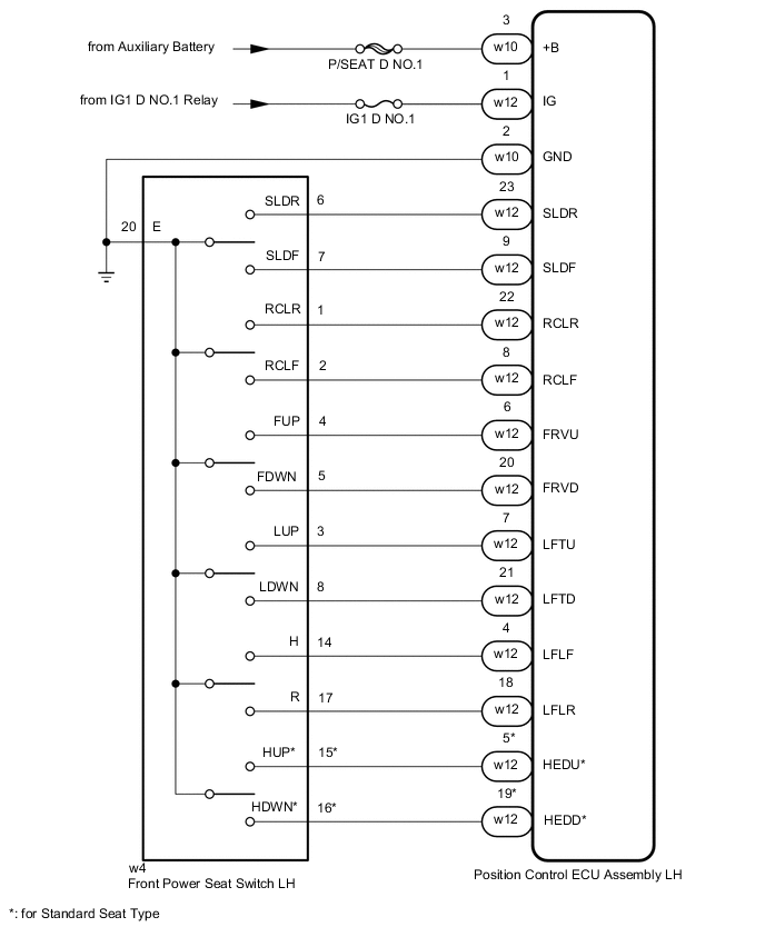
Figure 2. for RHD:

-
for Front Passenger Seat
Figure 3. for LHD:
Figure 4. for RHD:
CAUTION / NOTICE / HINT
Note
-
Inspect the fuses for circuits related to this system before performing the following procedure.
-
Initializing the position control ECU assembly will clear the seat position memory.
Tech Tips
-
Make sure to initialize the position control ECU assembly after replacing the seat assembly or any related parts (including removal and installation).
-
Before initializing the seat ECU, make sure that the D/C CUT fuse is normal.
-
When any of the following conditions are met, the seat position Information in the position control ECU assembly will be cleared.
-
The power switch is turned off with any of the seat switches being operated and the D/C CUT fuse removed.
-
The power switch is turned off within 1 second of any of the seat switches being operated with the D/C CUT fuse removed.
PROCEDURE
-
CHECK FRONT POWER SEAT OPERATION
-
Check that each function of the power seat operates normally by using the front power seat switch.
Result Result Proceed to All power seat functions do not operate (for Driver Seat) A All power seat functions do not operate (for Front Passenger Seat) B One or more power seat functions do not operate C
B 
CHECK HARNESS AND CONNECTOR (POSITION CONTROL ECU ASSEMBLY (FOR FRONT PASSENGER SEAT) - BATTERY) Click here
C 
GO TO OTHER DIAGNOSTIC PROCEDURE (One or more Power Seat Motors do not Operate) Click here
A 
-
-
CHECK HARNESS AND CONNECTOR (POSITION CONTROL ECU ASSEMBLY (FOR DRIVER SEAT) - BATTERY)
-
for LHD:
-
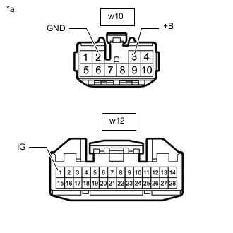
*a Front view of wire harness connector
(to Position Control ECU Assembly LH)
Disconnect the position control ECU assembly LH connectors.
-
Measure the resistance according to the value(s) in the table below.
Standard Resistnace Tester Connection Condition Specified Condition w10-2 (GND) - Body ground Always Below 1 Ω -
Measure the voltage according to the value(s) in the table below.
Standard Voltage Tester Connection Switch Condition Specified Condition w10-3 (+B) - Body ground Power switch off 11 to 14 V w12-1 (IG) - Body ground Power switch on (IG) 11 to 14 V Power switch off Below 1 V
-
-
for RHD:
-
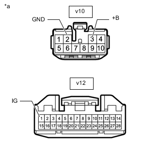
*a Front view of wire harness connector
(to Position Control ECU Assembly RH)
Disconnect the position control ECU assembly RH connectors.
-
Measure the resistance according to the value(s) in the table below.
Standard Resistnace Tester Connection Condition Specified Condition v10-2 (GND) - Body ground Always Below 1 Ω -
Measure the voltage according to the value(s) in the table below.
Standard Voltage Tester Connection Condition Specified Condition v10-3 (+B) - Body ground Power switch off 11 to 14 V v12-1 (IG) - Body ground Power switch on (IG) 11 to 14 V Power switch off Below 1 V
Result Proceed to OK NG -
NG
REPAIR OR REPLACE HARNESS OR CONNECTOR
OK
-
-
INSPECT FRONT POWER SEAT SWITCH (FOR DRIVER SEAT)
-
Remove the front power seat switch (for Driver Seat).
-
Inspect the front power seat switch (for Driver Seat).
Result Proceed to OK NG
NG
REPLACE FRONT POWER SEAT SWITCH (FOR DRIVER SEAT) Click here
OK
-
-
CHECK HARNESS AND CONNECTOR (FRONT POWER SEAT SWITCH (FOR DRIVER SEAT) - BODY GROUND)
-
for LHD:
-
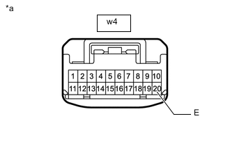
*a Front view of wire harness connector
(to Fronr Power Seat Switch LH)
Disconnect the front power seat switch LH connector.
-
Measure the resistance according to the value(s) in the table below.
Standard Resistance Tester Connection Condition Specified Condition w4-20 (GND) - Body ground Always Below 1 Ω
-
-
for RHD:
-
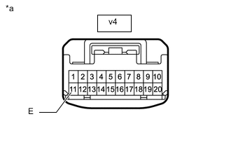
*a Front view of wire harness connector
(to Fronr Power Seat Switch RH)
Disconnect the front power seat switch RH connector.
-
Measure the resistance according to the value(s) in the table below.
Standard Resistance Tester Connection Condition Specified Condition v4-11 (GND) - Body ground Always Below 1 Ω
Result Proceed to OK NG -
OK
REPLACE POSITION CONTROL ECU ASSEMBLY (FOR DRIVER SEAT) Click here
NG
REPAIR OR REPLACE HARNESS OR CONNECTOR
-
-
CHECK HARNESS AND CONNECTOR (POSITION CONTROL ECU ASSEMBLY (FOR FRONT PASSENGER SEAT) - BATTERY)
-
for LHD:
-
*a Front view of wire harness connector
(to Position Control ECU Assembly RH)
Disconnect the position control ECU assembly RH connectors.
-
Measure the resistance according to the value(s) in the table below.
Standard Resistnace Tester Connection Condition Specified Condition v10-2 (GND) - Body ground Always Below 1 Ω -
Measure the voltage according to the value(s) in the table below.
Standard Voltage Tester Connection Switch Condition Specified Condition v10-3 (+B) - Body ground Power switch off 11 to 14 V v12-1 (IG) - Body ground Power switch on (IG) 11 to 14 V Power switch off Below 1 V
-
-
for RHD:
-
*a Front view of wire harness connector
(to Position Control ECU Assembly LH)
Disconnect the position control ECU assembly LH connectors.
-
Measure the resistance according to the value(s) in the table below.
Standard Resistnace Tester Connection Condition Specified Condition w10-2 (GND) - Body ground Always Below 1 Ω -
Measure the voltage according to the value(s) in the table below.
Standard Voltage Tester Connection Switch Condition Specified Condition w10-3 (+B) - Body ground Power switch off 11 to 14 V w12-1 (IG) - Body ground Power switch on (IG) 11 to 14 V Power switch off Below 1 V
Result Proceed to OK NG -
NG
REPAIR OR REPLACE HARNESS OR CONNECTOR
OK
-
-
INSPECT FRONT POWER SWITCH (FOR FRONT PASSENGER SEAT)
-
Remove the front power seat switch (for Front Passenger Seat).
-
Inspect the front power seat switch (for Front Passenger Seat).
Result Proceed to OK NG
NG
REPLACE FRONT POWER SEAT SWITCH (FOR FRONT PASSENGER SEAT) Click here
OK
-
-
CHECK HARNESS AND CONNECTOR (FRONT POWER SEAT SWITCH (FOR FRONT PASSENGER SEAT) - BODY GROUND)
-
for LHD:
-
*a Front view of wire harness connector
(to Fronr Power Seat Switch RH)
Disconnect the front power seat switch RH connector.
-
Measure the resistance according to the value(s) in the table below.
Standard Resistance Tester Connection Condition Specified Condition v4-11 (GND) - Body ground Always Below 1 Ω
-
-
for RHD:
-
*a Front view of wire harness connector
(to Fronr Power Seat Switch LH)
Disconnect the front power seat switch LH connector.
-
Measure the resistance according to the value(s) in the table below.
Standard Resistance Tester Connection Condition Specified Condition w4-20 (GND) - Body ground Always Below 1 Ω
Result Proceed to OK NG -
OK
REPLACE POSITION CONTROL ECU ASSEMBLY (FOR FRONT PASSENGER SEAT) Click here
NG
REPAIR OR REPLACE HARNESS OR CONNECTOR
-