FRONT POWER SEAT CONTROL SYSTEM, Diagnostic DTC:B2658
| DTC Code | DTC Name |
|---|---|
| B2658 | Short in Sensor with Motor Power Supply Circuit |
DESCRIPTION
-
*1: for LHD
-
*2: for RHD
-
*3: for Standard Seat Type
This DTC is stored when a power seat motor operates (a position control sensor is being supplied with power) and the power supply voltage does not rise to the specified value.
| DTC No. | Detection Item | DTC Detection Condition | Trouble Area |
|---|---|---|---|
| B2658 | Short in Sensor with Motor Power Supply Circuit | Problem with the voltage supplied to the position control sensor. |
|
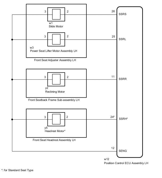
WIRING DIAGRAM
-
for Driver Seat
Figure 1. for LHD:

Figure 2. for RHD:
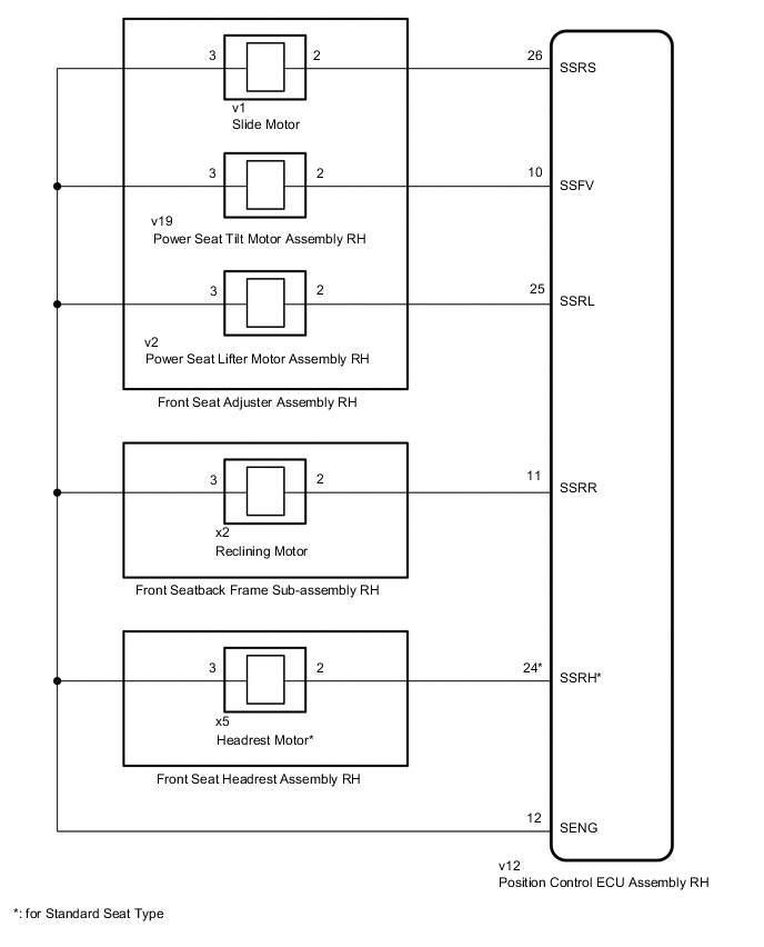
-
for Front Passenger Seat
Figure 3. for LHD:
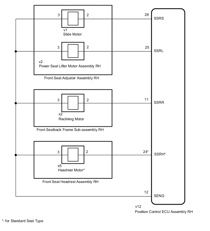
Figure 4. for RHD:
CAUTION / NOTICE / HINT
Note
Initializing the position control ECU assembly will clear the seat position memory.
Tech Tips
-
Make sure to initialize the position control ECU assembly after replacing the seat assembly or any related parts (including removal and installation).
-
Before initializing the seat ECU, make sure that the D/C CUT fuse is normal.
-
When any of the following conditions are met, the seat position Information in the position control ECU assembly will be cleared.
-
The power switch is turned off with any of the seat switches being operated and the D/C CUT fuse removed.
-
The power switch is turned off within 1 second of any of the seat switches being operated with the D/C CUT fuse removed.
PROCEDURE
-
CLEAR DTC
-
Clear the DTCs.
Body Electrical > Driver Seat > Clear DTCs
Body Electrical > Passenger Seat > Clear DTCsResult Proceed to NEXT
NEXT 
-
-
CHECK FOR DTC
-
Check for DTCs.
Body Electrical > Driver Seat > Trouble Codes
Body Electrical > Passenger Seat > Trouble CodesOK DTC B2658 is not output. Result Result Proceed to DTC B2658 is not output A DTC B2658 output from "Driver Seat" B DTC B2658 output from "Front Passenger Seat" C
A 
USE SIMULATION METHOD TO CHECK Click here
C 
CHECK HARNESS AND CONNECTOR (POSITION CONTROL ECU ASSEMBLY - FRONT SEAT ADJUSTER ASSEMBLY (SLIDE MOTOR)) Click here
B
-
-
CHECK HARNESS AND CONNECTOR (POSITION CONTROL ECU ASSEMBLY - FRONT SEAT ADJUSTER ASSEMBLY (SLIDE MOTOR))
-
for LHD:
-
Disconnect the w12 position control ECU assembly LH connector.
-
Disconnect the w1 front seat adjuster assembly LH (slide motor) connector.
-
Measure the resistance according to the value(s) in the table below.
Standard Resistance Tester Connection Condition Specified Condition w12-26 (SSRS) - w1-2 Always Below 1 Ω w12-26 (SSRS) or w1-2 - Other terminals and body ground Always 10 kΩ or higher w12-12 (SENG) - w1-3 Always Below 1 Ω
-
-
for RHD:
-
Disconnect the v12 position control ECU assembly RH connector.
-
Disconnect the v1 front seat adjuster assembly RH (slide motor) connector.
-
Measure the resistance according to the value(s) in the table below.
Standard Resistance Tester Connection Condition Specified Condition v12-26 (SSRS) - v1-2 Always Below 1 Ω v12-26 (SSRS) or v1-2 - Other terminals and body ground Always 10 kΩ or higher v12-12 (SENG) - v1-3 Always Below 1 Ω
Result Proceed to OK NG -
NG
REPAIR OR REPLACE HARNESS OR CONNECTOR
OK
-
-
CHECK POSITION CONTROL ECU ASSEMBLY (SLIDE MOTOR CIRCUIT)
-
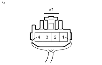
*a Front view of wire harness connector
(to Front Seat Adjuster Assembly LH (Slide Motor))
for LHD:
-
Disconnect the front seat adjuster assembly LH (slide motor) connector.
-
Measure the voltage according to the value(s) in the table below.
Standard Voltage Tester Connection Switch Condition Specified Condition w1-2 - w1-3 Slide switch on 4.8 to 5.1 V
-
-

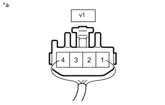
*a Front view of wire harness connector
(to Front Seat Adjuster Assembly RH (Slide Motor))
for RHD:
-
Disconnect the front seat adjuster assembly RH (slide motor) connector.
-
Measure the voltage according to the value(s) in the table below.
Standard Voltage Tester Connection Switch Condition Specified Condition v1-2 - v1-3 Slide switch on 4.8 to 5.1 V
Result Proceed to OK NG -
NG
REPLACE POSITION CONTROL ECU ASSEMBLY Click here
OK
-
-
CHECK HARNESS AND CONNECTOR (POSITION CONTROL ECU ASSEMBLY - POWER SEAT TILT MOTOR ASSEMBLY)
-
for LHD:
-
Disconnect the w12 position control ECU assembly LH connector.
-
Disconnect the w2 poewr seat tilt motor assembly LH connector.
-
Measure the resistance according to the value(s) in the table below.
Standard Resistance Tester Connection Condition Specified Condition w12-10 (SSFV) - w2-2 Always Below 1 Ω w12-10 (SSFV) or w2-2 - Other terminals and body ground Always 10 kΩ or higher w12-12 (SENG) - w2-3 Always Below 1 Ω
-
-
for RHD:
-
Disconnect the v12 position control ECU assembly RH connector.
-
Disconnect the v19 poewr seat tilt motor assembly RH connector.
-
Measure the resistance according to the value(s) in the table below.
Standard Resistance Tester Connection Condition Specified Condition v12-10 (SSFV) - v19-2 Always Below 1 Ω v12-10 (SSFV) or v19-2 - Other terminals and body ground Always 10 kΩ or higher v12-12 (SENG) - v19-3 Always Below 1 Ω
Result Proceed to OK NG -
NG
REPAIR OR REPLACE HARNESS OR CONNECTOR
OK
-
-
CHECK POSITION CONTROL ECU ASSEMBLY (TILT MOTOR CIRCUIT)
-

*a Front view of wire harness connector
(to Power Seat Tilt Motor Assembly LH)
for LHD:
-
Disconnect the power seat tilt motor assembly LH connector.
-
Measure the voltage according to the value(s) in the table below.
Standard Voltage Tester Connection Switch Condition Specified Condition w2-2 - w2-3 Tilt switch on 4.8 to 5.1 V
-
-
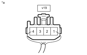
*a Front view of wire harness connector
(to Power Seat Tilt Motor Assembly RH)
for RHD:
-
Disconnect the power seat tilt motor assembly RH connector.
-
Measure the voltage according to the value(s) in the table below.
Standard Voltage Tester Connection Switch Condition Specified Condition v19-2 - v19-3 Tilt switch on 4.8 to 5.1 V
Result Proceed to OK NG -
NG
REPLACE POSITION CONTROL ECU ASSEMBLY Click here
OK
-
-
CHECK HARNESS AND CONNECTOR (POSITION CONTROL ECU ASSEMBLY - POWER SEAT LIFTER MOTOR ASSEMBLY)
-
for LHD:
-
Disconnect the w12 position control ECU assembly LH connector.
-
Disconnect the w3 poewr seat lifter motor assembly LH connector.
-
Measure the resistance according to the value(s) in the table below.
Standard Resistance Tester Connection Condition Specified Condition w12-25 (SSRL) - w3-2 Always Below 1 Ω w12-25 (SSRL) or w3-2 - Other terminals and body ground Always 10 kΩ or higher w12-12 (SENG) - w3-3 Always Below 1 Ω
-
-
for RHD:
-
Disconnect the v12 position control ECU assembly RH connector.
-
Disconnect the v2 poewr seat lifter motor assembly RH connector.
-
Measure the resistance according to the value(s) in the table below.
Standard Resistance Tester Connection Condition Specified Condition v12-25 (SSRL) - v2-2 Always Below 1 Ω v12-25 (SSRL) or v2-2 - Other terminals and body ground Always 10 kΩ or higher v12-12 (SENG) - v2-3 Always Below 1 Ω
Result Proceed to OK NG -
NG
REPAIR OR REPLACE HARNESS OR CONNECTOR
OK
-
-
CHECK POSITION CONTROL ECU ASSEMBLY (LIFTER MOTOR CIRCUIT)
-

*a Front view of wire harness connector
(to Power Seat Lifter Motor Assembly LH)
for LHD:
-
Disconnect the power seat lifter motor assembly LH connector.
-
Measure the voltage according to the value(s) in the table below.
Standard Voltage Tester Connection Switch Condition Specified Condition w3-2 - w3-3 Lifter switch on 4.8 to 5.1 V
-
-

*a Front view of wire harness connector
(to Power Seat Lifter Motor Assembly RH)
for RHD:
-
Disconnect the power seat lifter motor assembly RH connector.
-
Measure the voltage according to the value(s) in the table below.
Standard Voltage Tester Connection Switch Condition Specified Condition v2-2 - v2-3 Lifter switch on 4.8 to 5.1 V
Result Proceed to OK NG -
NG
REPLACE POSITION CONTROL ECU ASSEMBLY Click here
OK
-
-
CHECK HARNESS AND CONNECTOR (POSITION CONTROL ECU ASSEMBLY - FRONT SEATBACK FRAME SUB-ASSEMBLY (RECLINING MOTOR))
-
for LHD
-
Disconnect the w12 position control ECU assembly LH connector.
-
Disconnect the y2 front seatback frame sub-assembly LH (reclining motor) connector.
-
Measure the resistance according to the value(s) in the table below.
Standard Resistance Tester Connection Condition Specified Condition w12-11 (SSRR) - y2-2 Always Below 1 Ω w12-11 (SSRR) or y2-2 - Other terminals and body ground Always 10 kΩ or higher w12-12 (SENG) - y2-3 Always Below 1 Ω
-
-
for RHD
-
Disconnect the v12 position control ECU assembly RH connector.
-
Disconnect the x2 front seatback frame sub-assembly RH (reclining motor) connector.
-
Measure the resistance according to the value(s) in the table below.
Standard Resistance Tester Connection Condition Specified Condition v12-11 (SSRR) - x2-2 Always Below 1 Ω v12-11 (SSRR) or x2-2 - Other terminals and body ground Always 10 kΩ or higher v12-12 (SENG) - x2-3 Always Below 1 Ω
Result Proceed to OK NG -
NG
REPAIR OR REPLACE HARNESS OR CONNECTOR
OK
-
-
CHECK POSITION CONTROL ECU ASSEMBLY (RECLINING MOTOR CIRCUIT)
-

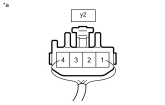
*a Front view of wire harness connector
(to Front Seatback Frame Sub-assembly LH (Reclining Motor))
for LHD:
-
Disconnect the front seatback frame sub-assembly LH (reclining motor) connector.
-
Measure the voltage according to the value(s) in the table below.
Standard Voltage Tester Connection Switch Condition Specified Condition y2-2 - y2-3 Reclining switch on 4.8 to 5.1 V
-
-

*a Front view of wire harness connector
(to Front Seatback Frame Sub-assembly RH (Reclining Motor))
for RHD:
-
Disconnect the front seatback frame sub-assembly RH (reclining motor) connector.
-
Measure the voltage according to the value(s) in the table below.
Standard Voltage Tester Connection Switch Condition Specified Condition x2-2 - x2-3 Reclining switch on 4.8 to 5.1 V
Result Result Proceed to OK (for Standard Seat Type) A OK (for Sports Seat Type) B NG C -
B
GO TO STEP 14 Click here
C
REPLACE POSITION CONTROL ECU ASSEMBLY Click here
A
-
-
CHECK HARNESS AND CONNECTOR (POSITION CONTROL ECU ASSEMBLY - FRONT SEAT HEADREST ASSEMBLY (HEADREST MOTOR))
-
for LHD:
-
Disconnect the w12 position control ECU assembly LH connector.
-
Disconnect the y5 front seat headrest assembly LH (headrest motor) connector.
-
Measure the resistance according to the value(s) in the table below.
Standard Resistance Tester Connection Condition Specified Condition w12-24 (SSRH) - y5-2 Always Below 1 Ω w12-24 (SSRH) or y5-2 - Other terminals and body ground Always 10 kΩ or higher w12-12 (SENG) - y5-3 Always Below 1 Ω
-
-
for RHD:
-
Disconnect the v12 position control ECU assembly RH connector.
-
Disconnect the x5 front seat headrest assembly RH (headrest motor) connector.
-
Measure the resistance according to the value(s) in the table below.
Standard Resistance Tester Connection Condition Specified Condition v12-24 (SSRH) - x5-2 Always Below 1 Ω v12-24 (SSRH) or x5-2 - Other terminals and body ground Always 10 kΩ or higher v12-12 (SENG) - x5-3 Always Below 1 Ω
Result Proceed to OK NG -
NG
REPAIR OR REPLACE HARNESS OR CONNECTOR
OK
-
-
CHECK POSITION CONTROL ECU ASSEMBLY (HEADRST MOTOR CIRCUIT)
-

*a Front view of wire harness connector
(to Front Seat Headrst Assembly LH (Headrset Motor))
for LHD:
-
Disconnect the front seat headrest assembly LH (headrest motor) connector.
-
Measure the voltage according to the value(s) in the table below.
Standard Voltage Tester Connection Switch Condition Specified Condition y5-2 - y5-3 Headrest switch on 4.8 to 5.1 V
-
-
*a Front view of wire harness connector
(to Front Seat Headrst Assembly RH (Headrset Motor))
for RHD:
-
Disconnect the front seat headrest assembly RH (headrest motor) connector.
-
Measure the voltage according to the value(s) in the table below.
Standard Voltage Tester Connection Switch Condition Specified Condition x5-2 - x5-3 Headrest switch on 4.8 to 5.1 V
Result Proceed to OK NG -
NG
REPLACE POSITION CONTROL ECU ASSEMBLY Click here
OK
-
-
CHECK FRONT SEAT HEADREST ASSEMBLY
-
Temporarily replace the front seat headrest assembly with a new or known good one.
-
Clear the DTCs.
Body Electrical > Driver Seat > Clear DTCs -
Check for DTCs.
Body Electrical > Driver Seat > Trouble CodesOK DTC B2658 is not output. Result Proceed to OK NG
OK
END (FRONT SEAT HEADREST ASSEMBLY WAS DEFECTIVE)
NG
-
-
CHECK POWER SEAT LIFTER MOTOR ASSEMBLY
-
Temporarily replace the power seat lifter motor assembly with a new or known good one.
-
Clear the DTCs.
Body Electrical > Driver Seat > Clear DTCs -
Check for DTCs.
Body Electrical > Driver Seat > Trouble CodesOK DTC B2658 is not output. Result Proceed to OK NG
OK
END (POWER SEAT LIFTER MOTOR ASSEMBLY WAS DEFECTIVE)
NG
-
-
CHECK POWER SEAT TILT MOTOR ASSEMBLY
-
Temporarily replace the power seat tilt motor assembly with a new or known good one.
-
Clear the DTCs.
Body Electrical > Driver Seat > Clear DTCs -
Check for DTCs.
Body Electrical > Driver Seat > Trouble CodesOK DTC B2658 is not output. Result Proceed to OK NG
OK
END (POWER SEAT TILT MOTOR ASSEMBLY WAS DEFECTIVE)
NG
-
-
CHECK FRONT SEAT ADJUSTER ASSEMBLY
-
Temporarily replace the front seat adjuster assembly with a new or known good one.
-
Clear the DTCs.
Body Electrical > Driver Seat > Clear DTCs -
Check for DTCs.
Body Electrical > Driver Seat > Trouble CodesOK DTC B2658 is not output. Result Proceed to OK NG
OK
END (FRONT SEAT ADJUSTER ASSEMBLY WAS DEFECTIVE)
NG
-
-
CHECK FRONT SEATBACK FRAME SUB-ASSEMBLY
-
Temporarily replace the front seatback frame sub-assembly with a new or known good one.
-
Clear the DTCs.
Body Electrical > Driver Seat > Clear DTCs -
Check for DTCs.
Body Electrical > Driver Seat > Trouble CodesOK DTC B2658 is not output. Result Proceed to OK NG
OK
END (FRONT SEATBACK FRAME SUB-ASSEMBLY WAS DEFECTIVE)
NG
REPLACE POSITION CONTROL ECU ASSEMBLY Click here
-
-
CHECK HARNESS AND CONNECTOR (POSITION CONTROL ECU ASSEMBLY - FRONT SEAT ADJUSTER ASSEMBLY (SLIDE MOTOR))
-
for LHD:
-
Disconnect the v12 position control ECU assembly RH connector.
-
Disconnect the v1 front seat adjuster assembly RH (slide motor) connector.
-
Measure the resistance according to the value(s) in the table below.
Standard Resistance Tester Connection Condition Specified Condition v12-26 (SSRS) - v1-2 Always Below 1 Ω v12-26 (SSRS) or v1-2 - Other terminals and body ground Always 10 kΩ or higher v12-12 (SENG) - v1-3 Always Below 1 Ω
-
-
for RHD:
-
Disconnect the w12 position control ECU assembly LH connector.
-
Disconnect the w1 front seat adjuster assembly LH (slide motor) connector.
-
Measure the resistance according to the value(s) in the table below.
Standard Resistance Tester Connection Condition Specified Condition w12-26 (SSRS) - w1-2 Always Below 1 Ω w12-26 (SSRS) or w1-2 - Other terminals and body ground Always 10 kΩ or higher w12-12 (SENG) - w1-3 Always Below 1 Ω
Result Proceed to OK NG -
NG
REPAIR OR REPLACE HARNESS OR CONNECTOR
OK
-
-
CHECK POSITION CONTROL ECU ASSEMBLY (SLIDE MOTOR CIRCUIT)
-
*a Front view of wire harness connector
(to Front Seat Adjuster Assembly RH (Slide Motor))
for LHD:
-
Disconnect the front seat adjuster assembly RH (slide motor) connector.
-
Measure the voltage according to the value(s) in the table below.
Standard Voltage Tester Connection Switch Condition Specified Condition v1-2 - v1-3 Slide switch on 4.8 to 5.1 V
Result Proceed to OK NG -
-

*a Front view of wire harness connector
(to Front Seat Adjuster Assembly LH (Slide Motor))
for RHD:
-
Disconnect the front seat adjuster assembly LH (slide motor) connector.
-
Measure the voltage according to the value(s) in the table below.
Standard Voltage Tester Connection Switch Condition Specified Condition w1-2 - w1-3 Slide switch on 4.8 to 5.1 V
-
NG
REPLACE POSITION CONTROL ECU ASSEMBLY Click here
OK
-
-
CHECK HARNESS AND CONNECTOR (POSITION CONTROL ECU ASSEMBLY - POWER SEAT LIFTER MOTOR ASSEMBLY)
-
for LHD:
-
Disconnect the v12 position control ECU assembly RH connector.
-
Disconnect the v2 power seat lifter motor assembly RH connector.
-
Measure the resistance according to the value(s) in the table below.
Standard Resistance Tester Connection Condition Specified Condition v12-25 (SSRL) - v2-2 Always Below 1 Ω v12-25 (SSRL) or v2-2 - Other terminals and body ground Always 10 kΩ or higher v12-12 (SENG) - v2-3 Always Below 1 Ω
-
-
for RHD:
-
Disconnect the w12 position control ECU assembly LH connector.
-
Disconnect the w3 power seat lifter motor assembly LH connector.
-
Measure the resistance according to the value(s) in the table below.
Standard Resistance Tester Connection Condition Specified Condition w12-25 (SSRL) - w3-2 Always Below 1 Ω w12-25 (SSRL) or w3-2 - Other terminals and body ground Always 10 kΩ or higher w12-12 (SENG) - w3-3 Always Below 1 Ω
Result Proceed to OK NG -
NG
REPAIR OR REPLACE HARNESS OR CONNECTOR
OK
-
-
CHECK POSITION CONTROL ECU ASSEMBLY (LIFTER MOTOR CIRCUIT)
-

*a Front view of wire harness connector
(to Power Seat Lifter Motor Assembly RH)
for LHD:
-
Disconnect the power seat lifter motor assembly RH connector.
-
Measure the voltage according to the value(s) in the table below.
Standard Voltage Tester Connection Switch Condition Specified Condition v2-2 - v2-3 Lifter switch on 4.8 to 5.1 V
-
-

*a Front view of wire harness connector
(to Power Seat Lifter Motor Assembly LH)
for RHD:
-
Disconnect the power seat lifter motor assembly LH connector.
-
Measure the voltage according to the value(s) in the table below.
Standard Voltage Tester Connection Switch Condition Specified Condition w3-2 - w3-3 Lifter switch on 4.8 to 5.1 V
Result Proceed to OK NG -
NG
REPLACE POSITION CONTROL ECU ASSEMBLY Click here
OK
-
-
CHECK HARNESS AND CONNECTOR (POSITION CONTROL ECU ASSEMBLY - FRONT SEATBACK FRAME SUB-ASSEMBLY (RECLINING MOTOR))
-
for LHD:
-
Disconnect the v12 position control ECU assembly RH connector.
-
Disconnect the x2 front seatback frame sub-assembly RH (reclining motor) connector.
-
Measure the resistance according to the value(s) in the table below.
Standard Resistance Tester Connection Condition Specified Condition v12-11 (SSRS) - x2-2 Always Below 1 Ω v12-11 (SSRR) or x2-2 - Other terminals and body ground Always 10 kΩ or higher v12-12 (SENG) - x2-3 Always Below 1 Ω
-
-
for RHD:
-
Disconnect the w12 position control ECU assembly LH connector.
-
Disconnect the y2 front seatback frame sub-assembly LH (reclining motor) connector.
-
Measure the resistance according to the value(s) in the table below.
Standard Resistance Tester Connection Condition Specified Condition w12-11 (SSRS) - y2-2 Always Below 1 Ω w12-11 (SSRR) or y2-2 - Other terminals and body ground Always 10 kΩ or higher w12-12 (SENG) - y2-3 Always Below 1 Ω
Result Proceed to OK NG -
NG
REPAIR OR REPLACE HARNESS OR CONNECTOR
OK
-
-
CHECK POSITION CONTROL ECU ASSEMBLY (RECLINING MOTOR CIRCUIT)
-

*a Front view of wire harness connector
(to Front Seatback Frame Sub-assembly RH (Reclining Motor))
for LHD:
-
Disconnect the front seatback frame sub-assembly RH (reclining motor) connector.
-
Measure the voltage according to the value(s) in the table below.
Standard Voltage Tester Connection Switch Condition Specified Condition x2-2 - x2-3 Reclining switch on 4.8 to 5.1 V
-
-
*a Front view of wire harness connector
(to Front Seatback Frame Sub-assembly LH (Reclining Motor))
for RHD:
-
Disconnect the front seatback frame sub-assembly LH (reclining motor) connector.
-
Measure the voltage according to the value(s) in the table below.
Standard Voltage Tester Connection Switch Condition Specified Condition y2-2 - y2-3 Reclining switch on 4.8 to 5.1 V
Result Result Proceed to OK (for Standard Seat Type) A OK (for Sports Seat Type) B NG C -
B
GO TO STEP 26 Click here
C
REPLACE POSITION CONTROL ECU ASSEMBLY Click here
A
-
-
CHECK HARNESS AND CONNECTOR (POSITION CONTROL ECU ASSEMBLY - FRONT SEAT HEADREST ASSEMBLY (HEADREST MOTOR))
-
for LHD:
-
Disconnect the v12 position control ECU assembly RH connector.
-
Disconnect the x5 front seat headrest assembly RH (headrest motor) connector.
-
Measure the resistance according to the value(s) in the table below.
Standard Resistance Tester Connection Condition Specified Condition v12-24 (SSRH) - x5-2 Always Below 1 Ω v12-24 (SSRH) or x5-2 - Other terminals and body ground Always 10 kΩ or higher v12-12 (SENG) - x5-3 Always Below 1 Ω
-
-
for RHD:
-
Disconnect the w12 position control ECU assembly LH connector.
-
Disconnect the y5 front seat headrest assembly LH (headrest motor) connector.
-
Measure the resistance according to the value(s) in the table below.
Standard Resistance Tester Connection Condition Specified Condition w12-24 (SSRH) - y5-2 Always Below 1 Ω w12-24 (SSRH) or y5-2 - Other terminals and body ground Always 10 kΩ or higher w12-12 (SENG) - y5-3 Always Below 1 Ω
Result Proceed to OK NG -
NG
REPAIR OR REPLACE HARNESS OR CONNECTOR
OK
-
-
CHECK POSITION CONTROL ECU ASSEMBLY (HEADREST MOTOR CIRCUIT)
-

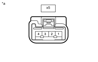
*a Front view of wire harness connector
(to Front Seat Headrest Assembly RH (Headrest Motor))
for LHD:
-
Disconnect the front seat headrest assembly RH (headrest motor) connector.
-
Measure the voltage according to the value(s) in the table below.
Standard Voltage Tester Connection Switch Condition Specified Condition x5-2 - x5-3 Headrest switch on 4.8 to 5.1 V
Result Proceed to OK NG -
-

*a Front view of wire harness connector
(to Front Seat Headrest Assembly LH (Headrest Motor))
for RHD:
-
Disconnect the front seat headrest assembly LH (headrest motor) connector.
-
Measure the voltage according to the value(s) in the table below.
Standard Voltage Tester Connection Switch Condition Specified Condition y5-2 - y5-3 Headrest switch on 4.8 to 5.1 V
-
NG
REPLACE POSITION CONTROL ECU ASSEMBLY Click here
OK
-
-
CHECK FRONT SEAT HEADREST ASSEMBLY
-
Temporarily replace the front seat headrest assembly with a new or known good one.
-
Clear the DTCs.
Body Electrical > Driver Seat > Clear DTCs -
Check for DTCs.
Body Electrical > Driver Seat > Trouble CodesOK DTC B2658 is not output. Result Proceed to OK NG
OK
END (FRONT SEAT HEADREST ASSEMBLY WAS DEFECTIVE)
NG
-
-
CHECK POWER SEAT LIFTER MOTOR ASSEMBLY
-
Temporarily replace the power seat lifter motor assembly with a new or known good one.
-
Clear the DTCs.
Body Electrical > Driver Seat > Clear DTCs -
Check for DTCs.
Body Electrical > Driver Seat > Trouble CodesOK DTC B2658 is not output. Result Proceed to OK NG
OK
END (POWER SEAT LIFTER MOTOR ASSEMBLY WAS DEFECTIVE)
NG
-
-
CHECK FRONT SEAT ADJUSTER ASSEMBLY
-
Temporarily replace the front seat adjuster assembly with a new or known good one.
-
Clear the DTCs.
Body Electrical > Driver Seat > Clear DTCs -
Check for DTCs.
Body Electrical > Driver Seat > Trouble CodesOK DTC B2658 is not output. Result Proceed to OK NG
OK
END (FRONT SEAT ADJUSTER ASSEMBLY WAS DEFECTIVE)
NG
-
-
CHECK FRONT SEATBACK FRAME SUB-ASSEMBLY
-
Temporarily replace the front seatback frame sub-assembly with a new or known good one.
-
Clear the DTCs.
Body Electrical > Driver Seat > Clear DTCs -
Check for DTCs.
Body Electrical > Driver Seat > Trouble CodesOK DTC B2658 is not output. Result Proceed to OK NG
OK
END (FRONT SEATBACK FRAME SUB-ASSEMBLY WAS DEFECTIVE)
NG
REPLACE POSITION CONTROL ECU ASSEMBLY Click here
-