KNEE AIRBAG ASSEMBLY(for Driver Side) INSTALLATION

CAUTION / NOTICE / HINT
Tech Tips
-
Use the same procedure as for the RHD and LHD vehicles.
-
The procedure listed below is for the LHD vehicles.
PROCEDURE
-
INSTALL LOWER NO. 1 INSTRUMENT PANEL AIRBAG ASSEMBLY
-
Check that the power switch is off.
-
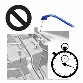
Check that the cable is disconnected from the negative (-) auxiliary battery terminal.
CAUTION:
-
Wait at least 90 seconds after disconnecting the cable from the negative (-) auxiliary battery terminal to disable the SRS system.
-
If the airbag deploys for any reason, it may cause a serious accident.
-
-
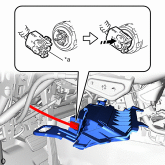
*a Lock Button 
Push in this Direction Connect the airbag connector and push the lock button to the lower No. 1 instrument panel airbag assembly.
Note
-
When connecting any airbag connector, take care not to damage the airbag wire harness.
-
Make sure the lock button is securely locked.
-
-
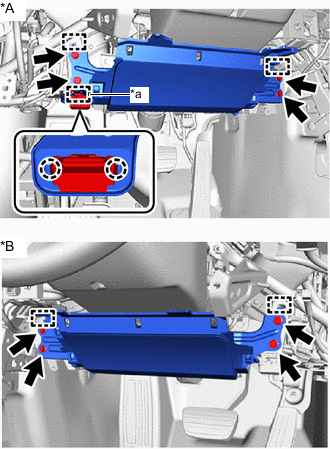
*A for LHD *B for RHD *a Wire Harness Clamp for LHD:
-
Attach the claws to connect the DLC3.
-
Attach the wire harness clamp.
-
-
Attach the hooks to temporarily install the lower No. 1 instrument panel airbag assembly.
-
Install the 4 bolts.
- Torque:
- 10 N*m { 102 kgf*cm, 7 ft.*lbf }
-
Check that there is no looseness in the lower No. 1 instrument panel airbag assembly.
-
-
INSTALL NO. 1 INSTRUMENT PANEL SAFETY PAD SUB-ASSEMBLY
-
INSTALL HOOD LOCK CONTROL LEVER SUB-ASSEMBLY
-
INSTALL NO. 1 INSTRUMENT PANEL UNDER COVER SUB-ASSEMBLY
-
INSTALL FRONT DOOR NO. 2 OPENING TRIM COVER LH
-
INSTALL FRONT DOOR OPENING TRIM COVER LH
-
INSTALL FRONT DOOR SCUFF PLATE LH
-
INSTALL BOX PANEL SUB-ASSEMBLY
-
INSTALL UPPER CONSOLE BOX
-
INSTALL SHIFTING HOLE COVER ASSEMBLY
-
INSTALL SHIFT LEVER KNOB SUB-ASSEMBLY
-
INSTALL RADIO REMOTE TUNING SWITCH ASSEMBLY
-
INSTALL REAR CONSOLE BOX POCKET
-
CONNECT CABLE TO NEGATIVE AUXILIARY BATTERY TERMINAL
Note
When disconnecting the cable, some systems need to be initialized after the cable is reconnected.
-
INSTALL NO. 2 DECK BOARD
-
PERFORM DIAGNOSTIC SYSTEM CHECK
-
CHECK SRS WARNING LIGHT