HEADUP DISPLAY SWITCH INSPECTION
PROCEDURE
-
INSPECT HEADUP DISPLAY SWITCH (NO. 3 COMBINATION SWITCH ASSEMBLY) (for LHD)
-
Remove the headup display switch (No. 3 combination switch assembly).
-
Check the resistance.
-
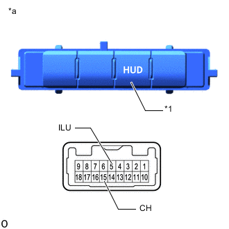
*1 HUD Switch *a Component without harness connected
(Headup Display Switch (No. 3 Combination Switch Assembly))
Measure the resistance according to the value(s) in the table below.
Standard Resistance Tester Connection Switch Condition Specified Condition 5 (ILU) - 15 (CH) HUD switch not pressed 10 kΩ or higher 5 (ILU) - 15 (CH) HUD switch pressed Below 1 Ω If the result is not as specified, replace the headup display switch (No. 3 combination switch assembly).
-
-
Check illumination.
-
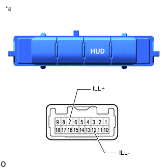
*a Component without harness connected
(Headup Display Switch (No. 3 Combination Switch Assembly))
Apply auxiliary battery voltage to the headup display switch and check that it illuminates.
OK Measurement Condition Specified Condition Auxiliary battery positive (+) → Terminal 7 (ILL+)
Auxiliary battery negative → Terminal 12 (ILL-)
Illuminates If the result is not as specified, replace the headup display switch (No. 3 combination switch assembly).
-
-
Install the headup display switch (No. 3 combination switch assembly).
-
-
INSPECT HEADUP DISPLAY SWITCH (NO. 3 COMBINATION SWITCH ASSEMBLY) (for RHD)
-
Remove the headup display switch (No. 3 combination switch assembly).
-
Check the resistance.
-
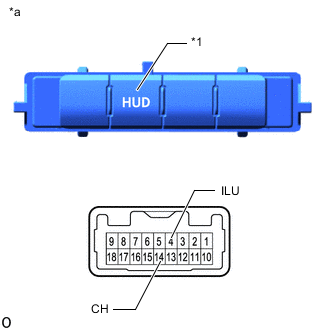
*1 HUD Switch *a Component without harness connected
(Headup Display Switch (No. 3 Combination Switch Assembly))
Measure the resistance according to the value(s) in the table below.
Standard Resistance Tester Connection Switch Condition Specified Condition 4 (ILU) - 14 (CH) HUD switch not pressed 10 kΩ or higher 4 (ILU) - 14 (CH) HUD switch pressed Below 1 Ω If the result is not as specified, replace the headup display switch (No. 3 combination switch assembly).
-
-
Check illumination.
-
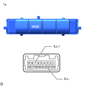
*a Component without harness connected
(Headup Display Switch (No. 3 Combination Switch Assembly))
Apply auxiliary battery voltage to the headup display switch and check that it illuminates.
OK Measurement Condition Specified Condition Auxiliary battery positive (+) → Terminal 7 (ILL+)
Auxiliary battery negative → Terminal 12 (ILL-)
Illuminates If the result is not as specified, replace the headup display switch (No. 3 combination switch assembly).
-
-
Install the headup display switch (No. 3 combination switch assembly).
-