POWER DOOR LOCK CONTROL SYSTEM All Doors LOCK/UNLOCK Functions do not Operate Via Door Key Cylinder
DESCRIPTION
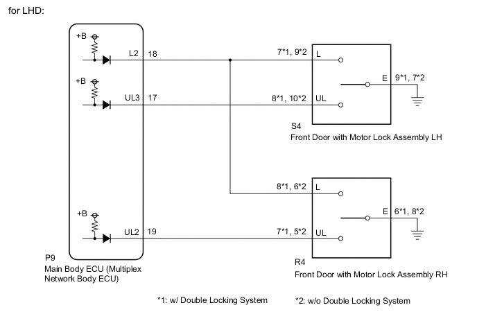
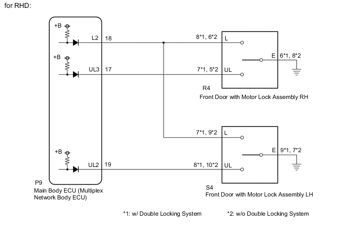
The main body ECU (multiplex network body ECU) receives door key cylinder lock or unlock switch signals from the front door with motor lock assembly LH/RH. The main body ECU (multiplex network body ECU) activates the door lock motor on each door according to these signals.
WIRING DIAGRAM
CAUTION / NOTICE / HINT
Note
If the main body ECU (multiplex network body ECU) is replaced, refer to the Service Bulletin.
PROCEDURE
-
CHECK PROBLEM SYMPTOM
-
Check the problem symptom.
Result Result Proceed to Key-linked lock/unlock function does not operate by driver door key cylinder A Key-linked lock/unlock function does not operate by front passenger door key cylinder B
B 
READ VALUE USING GTS (Door Key SW-Lock, Door Key SW-Unlock) Click here
A 
-
-
READ VALUE USING GTS (Door Key SW-Lock, D Door Key SW-UL)
-
Connect the GTS to the DLC3.
-
Turn the power switch on (IG).
-
Turn the GTS on.
-
Enter the following menus: Body Electrical / Main Body / Data List.
-
Read the Data List according to the display on the GTS.
Body Electrical > Main Body > Data ListTester Display Measurement Item Range Normal Condition Diagnostic Note Door Key SW-Lock Driver door key-linked switch lock signal OFF or ON OFF: Driver and front passenger door key cylinder not turned to lock position
ON: Driver door key cylinder turned to lock position
- D Door Key SW-UL Driver door key-linked switch unlock signal OFF or ON OFF: Driver door key cylinder not turned to unlock position
ON: Driver door key cylinder turned to unlock position
-
Body Electrical > Main Body > Data ListTester Display Door Key SW-Lock D Door Key SW-UL OK On the GTS screen, ON or OFF is displayed for each item according to the table above. Result Proceed to OK NG
OK 
REPLACE MAIN BODY ECU (MULTIPLEX NETWORK BODY ECU) Click here
NG
-
-
INSPECT FRONT DOOR WITH MOTOR LOCK ASSEMBLY (for Driver Door)
-
Remove the front door with motor lock assembly (for Driver Door).
-
Inspect the front door with motor lock assembly (for Driver Door).
Result Proceed to OK NG
NG
REPLACE FRONT DOOR WITH MOTOR LOCK ASSEMBLY (for Driver Door) Click here
OK
-
-
CHECK HARNESS AND CONNECTOR (FRONT DOOR WITH MOTOR LOCK ASSEMBLY (for Driver Door) - MAIN BODY ECU (MULTIPLEX NETWORK BODY ECU) AND BODY GROUND)
-
for LHD:
-
Disconnect the S4 front door with motor lock assembly LH connector.
-
Disconnect the R4 front door with motor lock assembly RH connector.
-
Disconnect the P9 main body ECU (multiplex network body ECU) connector.
-
Measure the resistance according to the value(s) in the table below.
Standard Resistance w/ Double Locking System Tester Connection Condition Specified Condition S4-7 (L) - P9-18 (L2) Always Below 1 Ω S4-8 (UL) - P9-17 (UL3) Always Below 1 Ω S4-9 (E) - Body ground Always Below 1 Ω S4-7 (L) or P9-18 (L2) - Other terminals and body ground Always 10 kΩ or higher S4-8 (UL) or P9-17 (UL3) - Other terminals and body ground Always 10 kΩ or higher Standard Resistance w/o Double Locking System Tester Connection Condition Specified Condition S4-9 (L) - P9-18 (L2) Always Below 1 Ω S4-10 (UL) - P9-17 (UL3) Always Below 1 Ω S4-7 (E) - Body ground Always Below 1 Ω S4-9 (L) or P9-18 (L2) - Other terminals and body ground Always 10 kΩ or higher S4-10 (UL) or P9-17 (UL3) - Other terminals and body ground Always 10 kΩ or higher
-
-
for RHD:
-
Disconnect the R4 front door with motor lock assembly RH connector.
-
Disconnect the S4 front door with motor lock assembly LH connector.
-
Disconnect the P9 main body ECU (multiplex network body ECU) connector.
-
Measure the resistance according to the value(s) in the table below.
Standard Resistance w/ Double Locking System Tester Connection Condition Specified Condition R4-8 (L) - P9-18 (L2) Always Below 1 Ω R4-7 (UL) - P9-17 (UL3) Always Below 1 Ω R4-6 (E) - Body ground Always Below 1 Ω R4-8 (L) or P9-18 (L2) - Other terminals and body ground Always 10 kΩ or higher R4-7 (UL) or P9-17 (UL3) - Other terminals and body ground Always 10 kΩ or higher Standard Resistance w/o Double Locking System Tester Connection Condition Specified Condition R4-6 (L) - P9-18 (L2) Always Below 1 Ω R4-5 (UL) - P9-17 (UL3) Always Below 1 Ω R4-8 (E) - Body ground Always Below 1 Ω R4-6 (L) or P9-18 (L2) - Other terminals and body ground Always 10 kΩ or higher R4-5 (UL) or P9-17 (UL3) - Other terminals and body ground Always 10 kΩ or higher
Result Proceed to OK NG -
OK
REPLACE MAIN BODY ECU (MULTIPLEX NETWORK BODY ECU) Click here
NG
REPAIR OR REPLACE HARNESS OR CONNECTOR
-
-
READ VALUE USING GTS (Door Key SW-Lock, Door Key SW-Unlock)
-
Connect the GTS to the DLC3.
-
Turn the power switch on (IG).
-
Turn the GTS on.
-
Enter the following menus: Body Electrical / Main Body / Data List.
-
Read the Data List according to the display on the GTS.
Body Electrical > Main Body > Data ListTester Display Measurement Item Range Normal Condition Diagnostic Note Door Key SW-Lock Front passenger door key-linked switch lock signal OFF or ON OFF: Driver and front passenger door key cylinder not turned to lock position
ON: Front passenger door key cylinder turned to lock position
- Door Key SW-Unlock Front passenger door key-linked switch unlock signal OFF or ON OFF: Front passenger door key cylinder not turned to unlock position
ON: Front passenger door key cylinder turned to unlock position
-
Body Electrical > Main Body > Data ListTester Display Door Key SW-Lock Door Key SW-Unlock OK On the GTS screen, ON or OFF is displayed for each item according to the table above. Result Proceed to OK NG
OK
REPLACE MAIN BODY ECU (MULTIPLEX NETWORK BODY ECU) Click here
NG
-
-
INSPECT FRONT DOOR WITH MOTOR LOCK ASSEMBLY (for Front Passenger Door)
-
Remove the front door with motor lock assembly (for Front Passenger Door).
-
Inspect the front door with motor lock assembly (for Front Passenger Door).
Result Proceed to OK NG
NG
REPLACE FRONT DOOR WITH MOTOR LOCK ASSEMBLY (for Front Passenger Door) Click here
OK
-
-
CHECK HARNESS AND CONNECTOR (FRONT DOOR WITH MOTOR LOCK ASSEMBLY (for Front Passenger Door) - MAIN BODY ECU (MULTIPLEX NETWORK BODY ECU) AND BODY GROUND)
-
for LHD:
-
Disconnect the R4 front door with motor lock assembly RH connector.
-
Disconnect the S4 front door with motor lock assembly LH connector.
-
Disconnect the P9 main body ECU (multiplex network body ECU) connector.
-
Measure the resistance according to the value(s) in the table below.
Standard Resistance w/ Double Locking System Tester Connection Condition Specified Condition R4-8 (L) - P9-18 (L2) Always Below 1 Ω R4-7 (UL) - P9-19 (UL2) Always Below 1 Ω R4-6 (E) - Body ground Always Below 1 Ω R4-8 (L) or P9-18 (L2) - Other terminals and body ground Always 10 kΩ or higher R4-7 (UL) or P9-19 (UL2) - Other terminals and body ground Always 10 kΩ or higher Standard Resistance w/o Double Locking System Tester Connection Condition Specified Condition R4-6 (L) - P9-18 (L2) Always Below 1 Ω R4-5 (UL) - P9-19 (UL2) Always Below 1 Ω R4-8 (E) - Body ground Always Below 1 Ω R4-6 (L) or P9-18 (L2) - Other terminals and body ground Always 10 kΩ or higher R4-5 (UL) or P9-19 (UL2) - Other terminals and body ground Always 10 kΩ or higher
-
-
for RHD:
-
Disconnect the S4 front door with motor lock assembly LH connector.
-
Disconnect the R4 front door with motor lock assembly RH connector.
-
Disconnect the P9 main body ECU (multiplex network body ECU) connector.
-
Measure the resistance according to the value(s) in the table below.
Standard Resistance w/ Double Locking System Tester Connection Condition Specified Condition S4-7 (L) - P9-18 (L2) Always Below 1 Ω S4-8 (UL) - P9-19 (UL2) Always Below 1 Ω S4-9 (E) - Body ground Always Below 1 Ω S4-7 (L) or P9-18 (L2) - Other terminals and body ground Always 10 kΩ or higher S4-8 (UL) or P9-19 (UL2) - Other terminals and body ground Always 10 kΩ or higher Standard Resistance w/o Double Locking System Tester Connection Condition Specified Condition S4-9 (L) - P9-18 (L2) Always Below 1 Ω S4-10 (UL) - P9-19 (UL2) Always Below 1 Ω S4-7 (E) - Body ground Always Below 1 Ω S4-9 (L) or P9-18 (L2) - Other terminals and body ground Always 10 kΩ or higher S4-10 (UL) or P9-19 (UL2) - Other terminals and body ground Always 10 kΩ or higher
Result Proceed to OK NG -
OK
REPLACE MAIN BODY ECU (MULTIPLEX NETWORK BODY ECU) Click here
NG
REPAIR OR REPLACE HARNESS OR CONNECTOR
-