CXPI COMMUNICATION SYSTEM, Diagnostic DTC:B2352, B2353, B2354
| DTC Code | DTC Name |
|---|---|
| B2352 | Lost Communication with Power Integration No.1 ECU |
| B2353 | Lost Communication with Power Integration No.2 ECU |
| B2354 | Lost Communication with Power Integration No.3 ECU |
DESCRIPTION
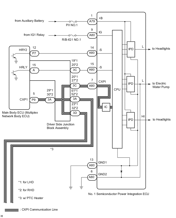
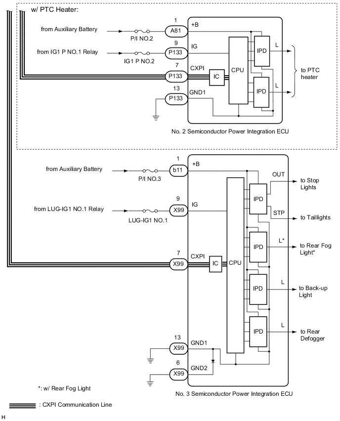
This DTC is stored when CXPI communication between the semiconductor power integration ECU and main body ECU (multiplex network body ECU) stops for 10 seconds or more.
| DTC No. | Detection Item | DTC Detection Condition | Trouble Area |
|---|---|---|---|
| B2352 | Lost Communication with Power Integration No.1 ECU | No communication between No. 1 semiconductor power integration ECU and main body ECU (multiplex network body ECU) for 10 seconds or more |
|
| B2353 | Lost Communication with Power Integration No.2 ECU | No communication between No. 2 semiconductor power integration ECU and main body ECU (multiplex network body ECU) for 10 seconds or more |
|
| B2354 | Lost Communication with Power Integration No.3 ECU | No communication between No. 3 semiconductor power integration ECU and main body ECU (multiplex network body ECU) for 10 seconds or more |
|
WIRING DIAGRAM
CAUTION / NOTICE / HINT
Note
-
When using the GTS with the power switch off to troubleshoot:
Connect the GTS to the vehicle and turn a courtesy light switch on and off at 1.5 second intervals until communication between the GTS and vehicle begins.
-
Inspect the fuses for circuits related to this system before performing the following inspection procedure.
-
Recognition code registration is necessary when replacing the main body ECU (multiplex network body ECU).
-
If the main body ECU (multiplex network body ECU) is replaced, refer to the Service Bulletin.
-
After turning the power switch off, waiting time may be required before disconnecting the cable from the negative (-) auxiliary battery terminal. Therefore, make sure to read the disconnecting the cable from the negative (-) auxiliary battery terminal notices before proceeding with work.
-
When disconnecting the cable from the negative (-) auxiliary battery terminal while performing repairs, some systems need to be initialized after the cable is reconnected.
PROCEDURE
-
CLEAR DTC
-
Clear the DTCs.
Body Electrical > Main Body > Clear DTCsResult Result NEXT
NEXT 
-
-
CHECK FOR DTC
-
Check for DTCs.
Body Electrical > Main Body > Trouble CodesResult Result Proceed to All DTCs are output A DTC B2352 is output B DTC B2353 is output (w/ PTC Heater) C DTC B2354 is output D
B 
CHECK HARNESS AND CONNECTOR (NO. 1 SEMICONDUCTOR POWER INTEGRATION ECU - BATTERY AND BODY GROUND) Click here
C
CHECK HARNESS AND CONNECTOR (NO. 2 SEMICONDUCTOR POWER INTEGRATION ECU - BATTERY AND BODY GROUND) Click here
D
CHECK HARNESS AND CONNECTOR (NO. 3 SEMICONDUCTOR POWER INTEGRATION ECU - BATTERY AND BODY GROUND) Click here
A
-
-
INSPECT DRIVER SIDE JUNCTION BLOCK ASSEMBLY
-
Remove the driver side junction block assembly.
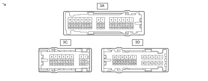
*a Component without harness connected
(Driver Side Junction Block Assembly)
- - -
Remove the main body ECU (multiplex network body ECU) from the driver side junction block assembly.
-
Measure the resistance according to the value(s) in the table below.
Standard Resistance *: w/ PTC Heaterfor LHD Tester Connection Condition Specified Condition 3A-29 - 3C-20 Always Below 1 Ω 3A-29 - 3A-51* Always Below 1 Ω 3A-29 - 3D-23 Always Below 1 Ω
for RHD Tester Connection Condition Specified Condition 3A-30 - 3C-27 Always Below 1 Ω 3A-30 - 3A-52* Always Below 1 Ω 3A-30 - 3D-32 Always Below 1 Ω *: w/ PTC Heater
Result Proceed to OK NG
NG 
REPLACE DRIVER SIDE JUNCTION BLOCK ASSEMBLY Click here
OK
-
-
CHECK HARNESS AND CONNECTOR (MAIN BODY ECU [MULTIPLEX NETWORK BODY ECU] - DRIVER SIDE JUNCTION BLOCK ASSEMBLY)
-
Disconnect the P9 main body ECU (multiplex network body ECU) connector.
-
Disconnect the 3A driver side junction block assembly connector.
-
Measure the resistance according to the value(s) in the table below.
Standard Resistance for LHD Tester Connection Condition Specified Condition P9-5 (CXP1) - 3A-29 Always Below 1 Ω P9-5 (CXP1) - Body ground Always 10 kΩ or higher for RHD Tester Connection Condition Specified Condition P9-5 (CXP1) - 3A-30 Always Below 1 Ω P9-5 (CXP1) - Body ground Always 10 kΩ or higher Result Proceed to OK NG
OK
REPLACE MAIN BODY ECU (MULTIPLEX NETWORK BODY ECU) Click here
NG
REPAIR OR REPLACE HARNESS OR CONNECTOR
-
-
CHECK HARNESS AND CONNECTOR (NO. 1 SEMICONDUCTOR POWER INTEGRATION ECU - BATTERY AND BODY GROUND)
-
Turn the power switch off.
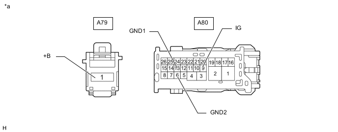
*a Front view of wire harness connector
(to No. 1 Semiconductor Power Integration ECU)
- - -
Disconnect the cable from the negative (-) auxiliary battery terminal.
-
Disconnect the A79 and A80 No. 1 semiconductor power integration ECU connectors.
-
Measure the resistance according to the value(s) in the table below.
Standard Resistance Tester Connection Condition Specified Condition A80-6 (GND2) - Body ground Always Below 1 Ω A80-13 (GND1) - Body ground Always Below 1 Ω -
Connect the cable to the negative (-) auxiliary battery terminal.
-
Measure the voltage according to the value(s) in the table below.
Standard Voltage Tester Connection Switch Condition Specified Condition A79-1 (+B) - Body ground Power switch off 8 to 14 V A80-9 (IG) - Body ground Power switch on (IG) 8 to 14 V Result Proceed to OK NG
NG
REPAIR OR REPLACE HARNESS OR CONNECTOR
OK
-
-
CHECK HARNESS AND CONNECTOR (MAIN BODY ECU [MULTIPLEX NETWORK BODY ECU] - NO. 1 SEMICONDUCTOR POWER INTEGRATION ECU)
-
Turn the power switch off.
-
Disconnect the cable from the negative (-) auxiliary battery terminal.
-
Disconnect the P9 main body ECU (multiplex network body ECU) connector.
-
Disconnect the A79 and A80 No. 1 semiconductor power integration ECU connectors.
-
Measure the resistance according to the value(s) in the table below.
Standard Resistance Tester Connection Condition Specified Condition A80-7 (CXPI) - P9-5 (CXP1) Always Below 1 Ω A80-7 (CXPI) - Body ground Always 10 kΩ or higher Result Proceed to OK NG
OK
REPLACE NO. 1 SEMICONDUCTOR POWER INTEGRATION ECU Click here
NG
-
-
CHECK HARNESS AND CONNECTOR (DRIVER SIDE JUNCTION BLOCK ASSEMBLY - NO. 1 SEMICONDUCTOR POWER INTEGRATION ECU)
-
Turn the power switch off.
-
Disconnect the cable from the negative (-) auxiliary battery terminal.
-
Disconnect the A79 and A80 No. 1 semiconductor power integration ECU connectors.
-
Disconnect the 3C driver side junction block assembly connector.
-
Measure the resistance according to the value(s) in the table below.
Standard Resistance for LHD Tester Connection Condition Specified Condition A80-7 (CXPI) - 3C-20 Always Below 1 Ω A80-7 (CXPI) - Body ground Always 10 kΩ or higher for RHD Tester Connection Condition Specified Condition A80-7 (CXPI) - 3C-27 Always Below 1 Ω A80-7 (CXPI) - Body ground Always 10 kΩ or higher Result Proceed to OK NG
OK
REPLACE DRIVER SIDE JUNCTION BLOCK ASSEMBLY Click here
NG
REPAIR OR REPLACE HARNESS OR CONNECTOR
-
-
CHECK HARNESS AND CONNECTOR (NO. 2 SEMICONDUCTOR POWER INTEGRATION ECU - BATTERY AND BODY GROUND)
-
Turn the power switch off.
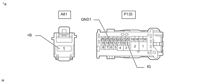
*a Front view of wire harness connector
(to No. 2 Semiconductor Power Integration ECU)
- - -
Disconnect the cable from the negative (-) auxiliary battery terminal.
-
Disconnect the A81 and P133 No. 1 semiconductor power integration ECU connectors.
-
Measure the resistance according to the value(s) in the table below.
Standard Resistance Tester Connection Condition Specified Condition P133-13 (GND) - Body ground Always Below 1 Ω -
Connect the cable to the negative (-) auxiliary battery terminal.
-
Measure the voltage according to the value(s) in the table below.
Standard Voltage Tester Connection Switch Condition Specified Condition A81-1 (+B) - Body ground Power switch off 8 to 14 V P133-9 (IG) - Body ground Power switch on (IG) 8 to 14 V Result Proceed to OK NG
NG
REPAIR OR REPLACE HARNESS OR CONNECTOR
OK
-
-
CHECK HARNESS AND CONNECTOR (MAIN BODY ECU [MULTIPLEX NETWORK BODY ECU] - NO. 2 SEMICONDUCTOR POWER INTEGRATION ECU)
-
Turn the power switch off.
-
Disconnect the cable from the negative (-) auxiliary battery terminal.
-
Disconnect the P9 main body ECU (multiplex network body ECU) connector.
-
Disconnect the A81 and P133 No. 2 semiconductor power integration ECU connectors.
-
Measure the resistance according to the value(s) in the table below.
Standard Resistance Tester Connection Condition Specified Condition P133-7 (CXPI) - P9-5 (CXP1) Always Below 1 Ω P133-7 (CXPI) - Body ground Always 10 kΩ or higher Result Proceed to OK NG
OK
REPLACE NO. 2 SEMICONDUCTOR POWER INTEGRATION ECU Click here
NG
-
-
CHECK HARNESS AND CONNECTOR (DRIVER SIDE JUNCTION BLOCK ASSEMBLY - NO. 2 SEMICONDUCTOR POWER INTEGRATION ECU)
-
Turn the power switch off.
-
Disconnect the cable from the negative (-) auxiliary battery terminal.
-
Disconnect the A81 and P133 No. 2 semiconductor power integration ECU connectors.
-
Disconnect the 3A driver side junction block assembly connector.
-
Measure the resistance according to the value(s) in the table below.
Standard Resistance for LHD Tester Connection Condition Specified Condition P133-7 (CXPI) - 3A-51 Always Below 1 Ω P133-7 (CXPI) - Body ground Always 10 kΩ or higher for LHD Tester Connection Condition Specified Condition P133-7 (CXPI) - 3A-52 Always Below 1 Ω P133-7 (CXPI) - Body ground Always 10 kΩ or higher Result Proceed to OK NG
OK
REPLACE DRIVER SIDE JUNCTION BLOCK ASSEMBLY Click here
NG
REPAIR OR REPLACE HARNESS OR CONNECTOR
-
-
CHECK HARNESS AND CONNECTOR (NO. 3 SEMICONDUCTOR POWER INTEGRATION ECU - BATTERY AND BODY GROUND)
-
Turn the power switch off.
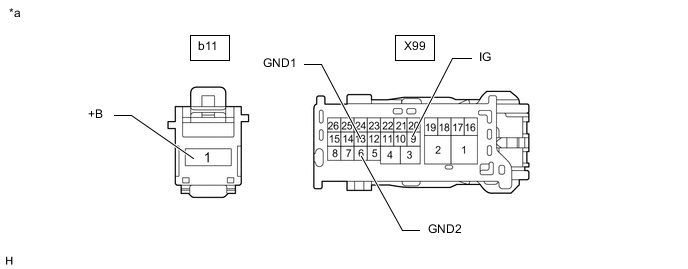
*a Front view of wire harness connector
(to No. 3 Semiconductor Power Integration ECU)
- - -
Disconnect the cable from the negative (-) auxiliary battery terminal.
-
Disconnect the b11 and X99 No. 3 semiconductor power integration ECU connectors.
-
Measure the resistance according to the value(s) in the table below.
Standard Resistance Tester Connection Condition Specified Condition X99-6 (GND2) - Body ground Always Below 1 Ω X99-13 (GND1) - Body ground Always Below 1 Ω -
Connect the cable to the negative (-) auxiliary battery terminal.
-
Measure the voltage according to the value(s) in the table below.
Standard Voltage Tester Connection Switch Condition Specified Condition b11-1 (+B) - Body ground Power switch off 8 to 14 V X99-9 (IG) - Body ground Power switch on (IG) 8 to 14 V Result Proceed to OK NG
NG
REPAIR OR REPLACE HARNESS OR CONNECTOR
OK
-
-
CHECK HARNESS AND CONNECTOR (MAIN BODY ECU [MULTIPLEX NETWORK BODY ECU] - NO. 3 SEMICONDUCTOR POWER INTEGRATION ECU)
-
Turn the power switch off.
-
Disconnect the cable from the negative (-) auxiliary battery terminal.
-
Disconnect the P9 main body ECU (multiplex network body ECU) connector.
-
Disconnect the b11 and X99 No. 3 semiconductor power integration ECU connectors.
-
Measure the resistance according to the value(s) in the table below.
Standard Resistance Tester Connection Condition Specified Condition X99-7 (CXPI) - P9-5 (CXP1) Always Below 1 Ω X99-7 (CXPI) - Body ground Always 10 kΩ or higher Result Proceed to OK NG
OK
REPLACE NO. 3 SEMICONDUCTOR POWER INTEGRATION ECU Click here
NG
-
-
CHECK HARNESS AND CONNECTOR (DRIVER SIDE JUNCTION BLOCK ASSEMBLY - NO. 3 SEMICONDUCTOR POWER INTEGRATION ECU)
-
Turn the power switch off.
-
Disconnect the cable from the negative (-) auxiliary battery terminal.
-
Disconnect the b11 and X99 No. 3 semiconductor power integration ECU connectors.
-
Disconnect the 3D driver side junction block assembly connector.
-
Measure the resistance according to the value(s) in the table below.
Standard Resistance for LHD Tester Connection Condition Specified Condition X99-7 (CXPI) - 3D-23 Always Below 1 Ω X99-7 (CXPI) - Body ground Always 10 kΩ or higher for RHD Tester Connection Condition Specified Condition X99-7 (CXPI) - 3D-32 Always Below 1 Ω X99-7 (CXPI) - Body ground Always 10 kΩ or higher Result Proceed to OK NG
OK
REPLACE DRIVER SIDE JUNCTION BLOCK ASSEMBLY Click here
NG
REPAIR OR REPLACE HARNESS OR CONNECTOR
-