INTEGRATION RELAY(for Instrument Panel Side) INSTALLATION
CAUTION / NOTICE / HINT
Tech Tips
-
Use the same procedure for RHD and LHD vehicles.
-
The procedure listed below is for LHD vehicles.
PROCEDURE
-
INSTALL NO. 2 SEMICONDUCTOR POWER INTEGRATION ECU
-
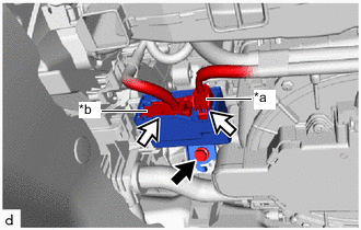
*a Power Supply Connector *b Lever Connector 
Bolt 
Connector Connect the power supply connector and lever connector to install the No. 2 semiconductor power integration ECU.
Note
-
Do not touch the No. 2 semiconductor power integration ECU connector.
-
When removing the No. 2 semiconductor power integration ECU, take care not to damage it.
-
Do not use a No. 2 semiconductor power integration ECU that has been dropped or subjected to a strong shock.
-
-
Install the bolt.
- Torque:
- 8.0 N*m { 82 kgf*cm, 71 in.*lbf }
-
-
INSTALL NO. 1 INSTRUMENT PANEL UNDER COVER SUB-ASSEMBLY
-
CONNECT CABLE TO NEGATIVE AUXILIARY BATTERY TERMINAL
Note
When disconnecting the cable, some systems need to be initialized after the cable is reconnected.
-
INSTALL NO. 2 DECK BOARD