SUB BATTERY SYSTEM, Diagnostic DTC:B22DA
| DTC Code | DTC Name |
|---|---|
| B22DA | Sub Battery Module Protection Relay Stuck Close |
DESCRIPTION
| DTC No. | Detection Item | DTC Detection Condition | Trouble Area | Warning Indicate | Memory |
|---|---|---|---|---|---|
| B22DA | Sub Battery Module Protection Relay Stuck Close | This DTC is stored when the protection relay is stuck closed continuously for 10 seconds. (1 trip detection logic) |
Sub-battery module assembly | Comes on | DTC stored |
Tech Tips
The details of a DTC can be checked by using the DTC Sub Code of the freeze frame data that was recorded when the DTC was output.
| DTC Sub Code | Detail |
|---|---|
| "30" | CNT V2 Voltage is 6.0 V or more and Protection Relay Circuit Voltage is 6 V or less |
WIRING DIAGRAM
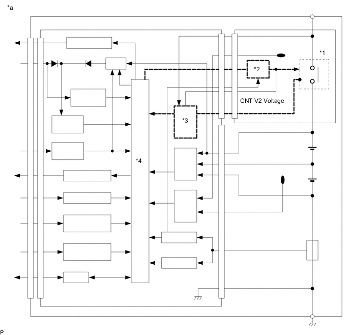
| *a | Sub-battery Module Assembly | - | - |
| *1 | Protection relay | *2 | Protection relay drive circuit |
| *3 | Voltage detection circuit | *4 | CPU |
CAUTION / NOTICE / HINT
Tech Tips
Read freeze frame data using the GTS. Freeze frame data records the sub-battery module assembly condition when malfunctions are detected.
PROCEDURE
-
REPLACE SUB-BATTERY MODULE ASSEMBLY
Note
If B22DA is output, the protective relay inside the sub-battery module assembly is stuck closed. As a result, sub-battery voltage is output from +BAT terminal normally.
Take care when removing the sub-battery module assembly.
-
Refer to the following procedures for removing the connector cover from the deck board.
-
Remove the sub-battery module assembly.
-
Loosen the 2 nuts and disconnect the 2 sub-battery terminals from the sub-battery module assembly.
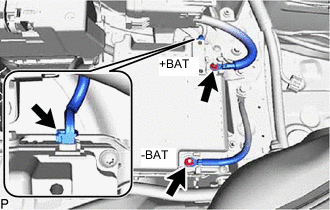
Note
To prevent shorts in the +BAT and -BAT terminals in the removed sub-battery, wrap them in protective tape.
-
Disconnect the connector from the sub-battery module assembly.
-
Loosen the 2 bolts and 2 nuts and remove from the sub-battery module assembly.
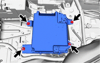
-
-
Install the sub-battery module assembly.
Result Proceed to NEXT
NEXT 
END
-