SUB BATTERY SYSTEM SYSTEM DESCRIPTION
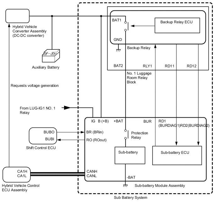
The sub battery system is composed of a sub-battery module assembly and backup relay. If a malfunction occurs in the auxiliary battery, the system maintains the functions of connected vehicle electrical loads after the malfunction occurs.
The sub-battery module assembly is composed of a sub-battery, sub-battery ECU and protection relay.
| Component | Description |
|---|---|
| Sub-battery Module Assembly | Part that is built into the sub-battery, monitors the sub-battery and includes backup control. |
| Sub-battery ECU | Part that is built into the sub-battery module assembly, monitors the sub-battery and performs backup control. |
| Backup Relay |
|
| Protection Relay | Relay that is built into the sub-battery module assembly and outputs power from the sub-battery/stops the sub-battery |
| Shift Control ECU | The shift control ECU requests power supply to the sub-battery ECU inside the sub-battery module assembly from the sub-battery when the auxiliary battery voltage is low. |
| Hybrid Vehicle Control ECU Assembly | Hybrid vehicle control ECU assembly controls the voltage of hybrid vehicle converter assembly (DC-DC converter) based a request from sub-battery ECU. |
| Terminal | Description |
|---|---|
| +BAT |
|
| -BAT | |
| B (+B) | Sub-battery ECU power source terminal |
| IG | IG signal input terminal |
| CANH | CAN communication terminal |
| CANL | |
| BR (BRin) | Receives backup requests from shift control ECU |
| RD1 (BURDIAG1) | Acquires backup relay condition information |
| RD2 (BURDIAG2) | Acquires backup relay malfunction information |
| RO (ROout) | Sends sub-battery condition to shift control ECU |
| BUR | Outputs backup relay ON control signal |
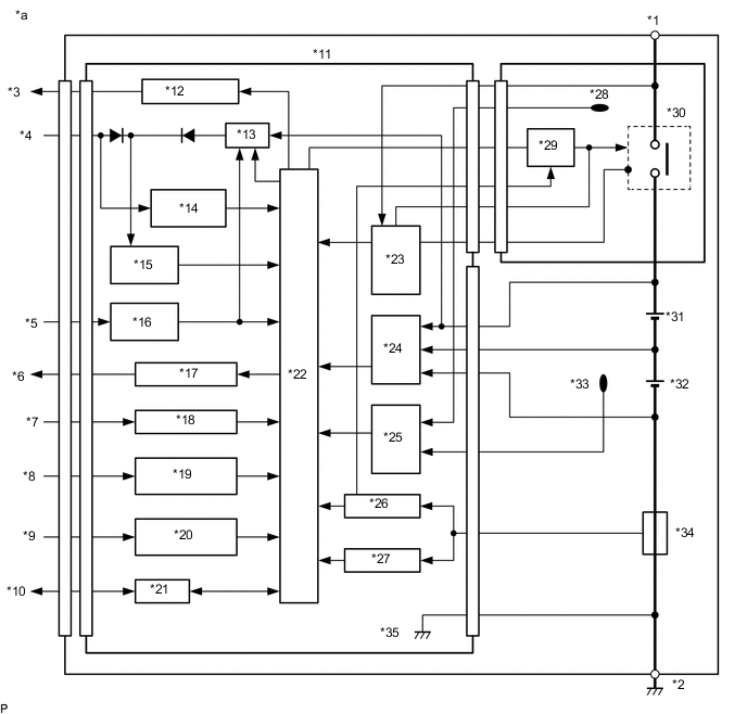
| *a | Sub-battery Module Assembly | - | - |
| *1 | +BAT | *2 | -BAT |
| *3 | BUR Output | *4 | B (+B) Input |
| *5 | IG input | *6 | RO (ROout) Output |
| *7 | BR (BRin) Input | *8 | RD1 (BURDIAG1) Input |
| *9 | RD2 (BURDIAG2) Input | *10 | CAN Input and Output |
| *11 | Sub-battery ECU | *12 | BUR Output Circuit |
| *13 | +B Backup Power Source Circuit | *14 | Auxiliary Battery Voltage Detection Circuit |
| *15 | Power Source Circuit | *16 | IGN Input Detection Circuit |
| *17 | RO (ROout) output circuit | *18 | BR (BRin) Input Circuit |
| *19 | RD1 (BURDIAG1) input circuit | *20 | RD2 (BURDIAG2) Input Circuit |
| *21 | CAN | *22 | CPU |
| *23 | Voltage Detection Circuit | *24 | Voltage Detection Circuit |
| *25 | Temperature Detection Circuit | *26 | Overcurrent Protection Circuit |
| *27 | Current Detection Circuit | *28 | Protection Relay Temperature Sensor |
| *29 | Protection Relay Drive Circuit | *30 | Protection Relay |
| *31 | Sub-battery (Hi) | *32 | Sub-battery (Low) |
| *33 | Sub-battery Temperature Sensor | *34 | Sub-battery Current Sensor |
| *35 | GND | - | - |