PARKING ASSIST MONITOR SYSTEM Reverse Signal Circuit
DESCRIPTION
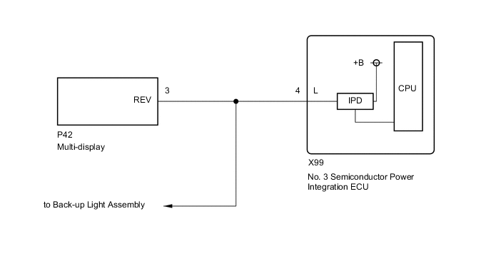
The multi-display receives a reverse signal from the No. 3 semiconductor power integration ECU.
WIRING DIAGRAM
CAUTION / NOTICE / HINT
Note
-
If the cable was disconnected from and reconnected to the negative (-) auxiliary battery terminal, the estimated course lines may not be displayed on the image of the area behind the vehicle. In this case, perform "Correct the Steering Angle Neutral Point".
-
Depending on the parts that are replaced or operations that are performed during vehicle inspection or maintenance, calibration of other systems as well as the parking assist monitor system may be needed.
PROCEDURE
-
CHECK BACK-UP LIGHT
-
Check that the back-up light comes on.
OK The back-up light comes on. Result Proceed to OK NG
NG 
GO TO LIGHTING SYSTEM (EXT) Click here
OK 
-
-
CHECK HARNESS AND CONNECTOR (REVERSE SIGNAL)
-
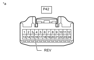
*a Front view of wire harness connector
(to Multi-display)
Disconnect the multi-display connector.
-
Measure the voltage according to the value(s) in the table below.
Standard Voltage Tester Connection Condition Specified Condition P42-3 (REV) - Body ground Power switch on (READY)
Shift position in R
8 to 14 V P42-3 (REV) - Body ground Power switch on (READY)
Shift position not in R
Below 1 V Result Proceed to OK NG
OK
PROCEED TO NEXT SUSPECTED AREA SHOWN IN PROBLEM SYMPTOMS TABLE Click here
NG
REPAIR OR REPLACE HARNESS OR CONNECTOR
-