BRAKE ACTUATOR(for RHD) INSTALLATION

CAUTION / NOTICE / HINT
Note
While the auxiliary battery is connected, even if the power switch is off, the brake control system activates when the brake pedal is depressed or any door courtesy switch is turned on. Therefore, when servicing brake system components, do not depress the brake pedal or open/close the doors while the auxiliary battery is connected.
PROCEDURE
-
INSTALL NO. 3 BRAKE ACTUATOR BRACKET
-
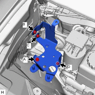
Install the No. 3 brake actuator bracket to the body with the 4 bolts.
- Torque:
- 11 N*m { 112 kgf*cm, 8 ft.*lbf }
Note
Tighten the 4 bolts uniformly in alphabetical order.
-
-
INSTALL NO. 1 BRAKE ACTUATOR BRACKET
-
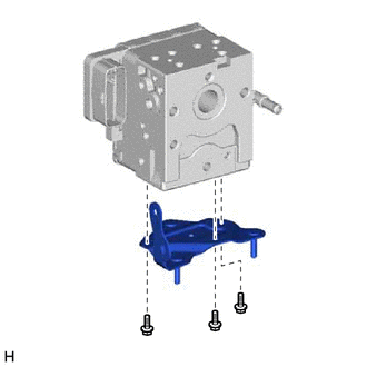
Install the No. 1 brake actuator bracket to the brake actuator assembly with the 3 bolts.
- Torque:
- 9.3 N*m { 95 kgf*cm, 82 in.*lbf }
-
-
INSTALL NO. 2 BRAKE ACTUATOR BRACKET
-
Install the 3 brake actuator bracket cushions to the No. 2 brake actuator bracket.
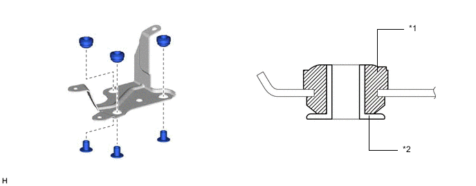
*1 Brake Actuator Bracket Cushion *2 Brake Actuator Bracket Spacer -
Install the 3 brake actuator bracket spacers to the brake actuator bracket cushion.
-
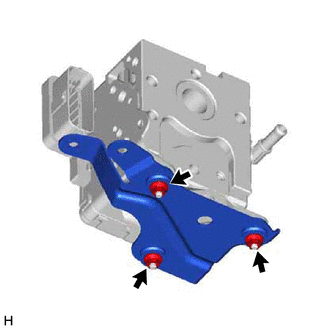
Install the No. 2 brake actuator bracket to the brake actuator assembly with the 3 nuts.
- Torque:
- 9.3 N*m { 95 kgf*cm, 82 in.*lbf }
-
-
INSTALL NO. 1 BRAKE ACTUATOR WAY
-
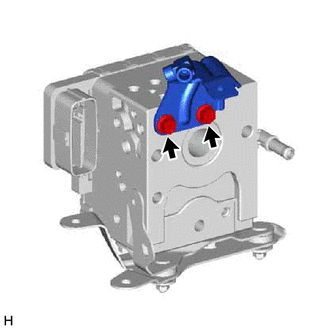
Install the No. 1 brake actuator way to the brake actuator assembly with the 2 bolts.
- Torque:
- 19 N*m { 194 kgf*cm, 14 ft.*lbf }
-
-
INSTALL NO. 3 BRAKE ACTUATOR TUBE
-
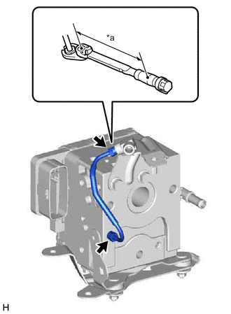
*a Torque Wrench Fulcrum Length Temporarily install the No. 3 brake actuator tube to the brake actuator assembly and No. 1 brake actuator way.
-
Using a union nut wrench, tighten the No. 3 brake actuator tube.
- Torque:
- Specified tightening torque
- 15.2 N*m { 155 kgf*cm, 11 ft.*lbf }
Note
-
Do not kink or damage the No. 3 brake actuator tube.
-
Do not allow any foreign matter such as dirt or dust to enter the No. 3 brake actuator tube from the connecting parts.
Tech Tips
-
Calculate the torque wrench reading when changing the fulcrum length of the torque wrench.
-
When using a union nut wrench (fulcrum length of 22 mm (0.8661 in.)) + torque wrench (fulcrum length of 162 mm (6.3779 in.)): 13.4 N*m (137 kgf*cm, 10 ft.*lbf)
-
-
INSTALL BRAKE ACTUATOR HOSE
-
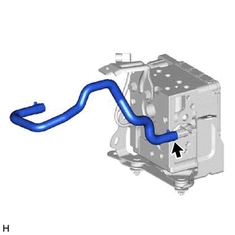
Connect the brake actuator hose to the brake actuator assembly, and slide the clamp to secure it.
-
-
INSTALL BRAKE ACTUATOR WITH BRACKET
-
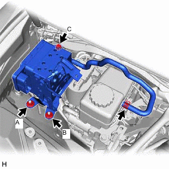
Install the brake actuator with bracket with the bolt and 2 nuts.
- Torque:
- 19 N*m { 194 kgf*cm, 14 ft.*lbf }
Note
-
Tighten the bolt and 2 nuts uniformly in alphabetical order.
-
Do not kink or damage the brake tube.
-
Do not hold the brake actuator with bracket by the connector, hose or union.
-
Do not allow any foreign matter such as dirt or dust to enter the brake lines from the connecting parts.
-
Do not drop the brake actuator assembly. Do not use parts that have been dropped.
Tech Tips
Install the brake actuator with bracket while avoiding the brake tubes.
-
Connect the brake actuator hose to the brake master cylinder reservoir, and slide the clamp to secure it
-
-
INSTALL BRAKE TUBE
-
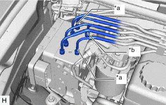
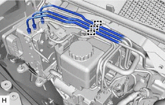
*a From Brake Stroke Simulator Cylinder Sub-assembly *b From Brake Master Cylinder Sub-assembly Tighten the 3 brake lines to the correct positions on the brake actuator assembly as shown in the illustration.
-
Temporarily install the 6 brake tube flare nuts.
-
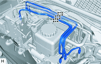
Attach the 3 brake tubes with a new clamp.
-
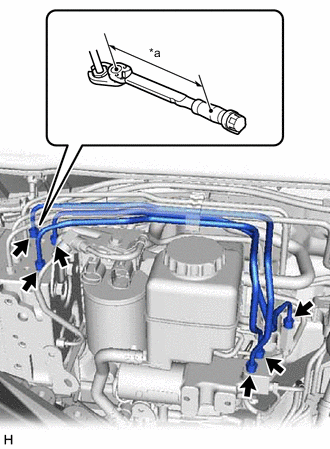
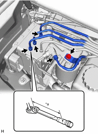
*a Torque Wrench Fulcrum Length Using a union nut wrench, tighten the 6 brake tube flare nuts.
- Torque:
- Specified tightening torque
- 15.2 N*m { 155 kgf*cm, 11 ft.*lbf }
Tech Tips
-
Calculate the torque wrench reading when changing the fulcrum length of the torque wrench.
-
When using a union nut wrench (fulcrum length of 22 mm (0.8661 in.)) + torque wrench (fulcrum length of 162 mm (6.3779 in.)): 13.4 N*m (137 kgf*cm, 10 ft.*lbf)
-
-
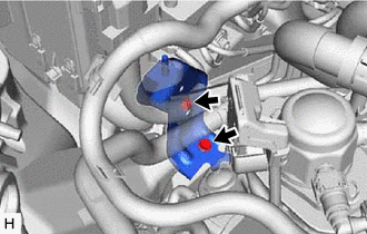
CONNECT BRAKE TUBE
-
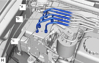
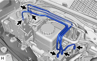
*a To Rear Wheel Cylinder Assembly RH *b To Rear Wheel Cylinder Assembly LH *c To Front Wheel Cylinder Assembly LH Tighten the 3 brake lines to the correct positions on the brake actuator assembly as shown in the illustration.
-
Attach the claws and connect the 3 upper side brake tubes to the clam.
-
*a Torque Wrench Fulcrum Length Temporarily install the 4 brake tube flare nuts.
-
Connect the No. 2 brake actuator tube with the bolt.
- Torque:
- 8.0 N*m { 82 kgf*cm, 71 in.*lbf }
-
Using a union nut wrench, tighten the 4 brake tube flare nuts.
- Torque:
- Specified tightening torque
- 15.2 N*m { 155 kgf*cm, 11 ft.*lbf }
Note
-
Do not kink or damage the brake tube.
-
Do not allow any foreign matter such as dirt or dust to enter the brake tube from the connecting parts.
Tech Tips
-
Calculate the torque wrench reading when changing the fulcrum length of the torque wrench.
-
When using a union nut wrench (fulcrum length of 22 mm (0.8661 in.)) + torque wrench (fulcrum length of 162 mm (6.3779 in.)): 13.4 N*m (137 kgf*cm, 10 ft.*lbf)
-
-
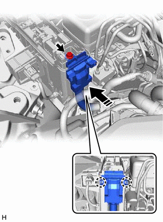
CONNECT WIRE HARNESS
-
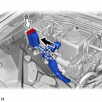

Connector Connected 
Lock Lever Locked Connect the 2 clips.
-
Connect the brake actuator connector to the brake actuator assembly and lock the lock lever.
Note
-
Make sure that the connector is locked securely.
-
Make sure that the actuator connector can be connected smoothly. Do not allow water, oil or dirt to enter the connector.
-
-
-
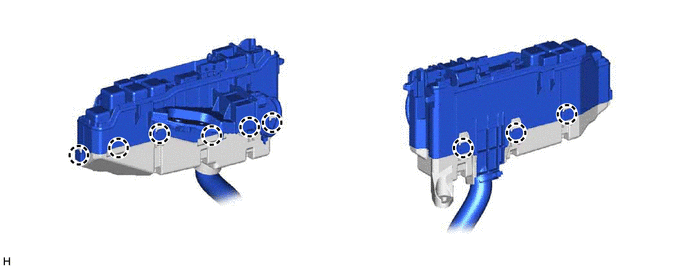
INSTALL RELAY BLOCK
-
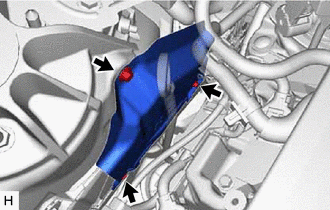
Install the wire harness clamp bracket with the bolt.
- Torque:
- 8.0 N*m { 82 kgf*cm, 71 in.*lbf }
-
Connect the wire harness clamp with the bolt.
- Torque:
- 8.0 N*m { 82 kgf*cm, 71 in.*lbf }
-
Attach the 9 claws and install the relay block lower cover.
-
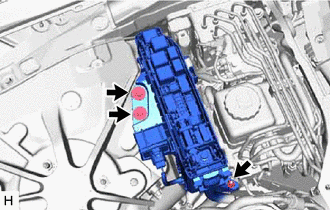
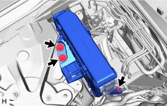
Temporarily install the relay block with the 2 bolts and nut.
-
Attach the 2 claws and install the Wiring harness protector.
-
Install the bolt.
- Torque:
- 10 N*m { 102 kgf*cm, 7 ft.*lbf }
-
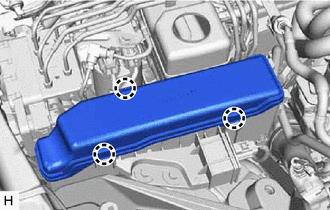
Attach the 3 claws and install the No. 2 relay block cover.
-
Tighten the 2 bolts and nut.
- Torque:
- 8.0 N*m { 82 kgf*cm, 71 in.*lbf }
-
-
INSTALL FRONT APRON FENDER INSULATOR RH
-
Install the front apron fender insulator RH with the 3 bolts.
- Torque:
- 5.4 N*m { 55 kgf*cm, 48 in.*lbf }
-
-
INSTALL AIR CLEANER WITH AIR CLEANER HOSE
-
INSTALL NO. 1 AIR CLEANER INLET
-
INSTALL FENDER APRON BRACE SUB-ASSEMBLY RH
-
CONNECT CABLE TO NEGATIVE AUXILIARY BATTERY TERMINAL
Note
Make sure that the 2 brake booster pump connectors are disconnected.
-
BLEED BRAKE SYSTEM
-
PERFORM INITIALIZATION AND CALIBRATION OF LINEAR SOLENOID VALVE
-
CHECK AND CLEAR DTC