BRAKE ACTUATOR(for RHD) REMOVAL

CAUTION / NOTICE / HINT
The necessary procedures (adjustment, calibration, initialization, or registration) that must be performed after parts are removed, installed, or replaced during brake actuator assembly removal/installation are shown below.
| Replaced Part or Performed Procedure | Necessary Procedure | Effect/Inoperative Function when Necessary Procedure not Performed | Link |
|---|---|---|---|
| Auxiliary battery terminal is disconnected/reconnected | Memorize steering angle neutral point | LKA/LDA system | |
| Pre-collision system | |||
| Parking assist monitor system | |||
| Steering sensor zero point calibration | Variable gear ratio steering system | ||
| Replacement of brake actuator assembly |
|
|
|
CAUTION / NOTICE / HINT
Note
While the auxiliary battery is connected, even if the power switch is off, the brake control system activates when the brake pedal is depressed or any door courtesy switch is turned on. Therefore, when servicing brake system components, do not depress the brake pedal or open/close the doors while the auxiliary battery is connected.
PROCEDURE
-
PRECAUTION
Note
After turning the power switch off, waiting time may be required before disconnecting the cable from the negative (-) auxiliary battery terminal. Therefore, make sure to read the disconnecting the cable from the negative (-) auxiliary battery terminal notices before proceeding with work.
-
DISCONNECT BRAKE BOOSTER PUMP CONNECTOR
-
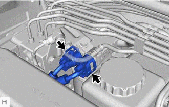
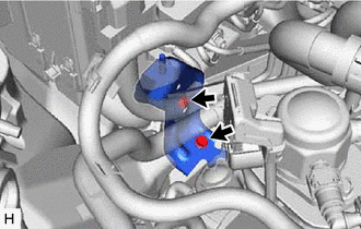
With the power switch off, disconnect the 2 brake booster pump connectors.
-
-
PERFORM ACCUMULATOR PRESSURE ZERO DOWN
-
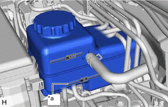
*a MIN Line Drain the brake fluid in the brake master cylinder reservoir assembly to near the MIN line.
-
Connect the GTS to the DLC3 with the power switch off.
-
Check that the parking brake is applied, and turn the power switch on (IG).
-
Turn the GTS on and enter the following menus: Chassis / ABS/VSC/TRAC / Utility / ECB (Electronically Controlled Brake System) Utility / Zero Down.
Chassis > ABS/VSC/TRAC > UtilityTester Display ECB Utility Tech Tips
Using the GTS to perform accumulator pressure zero down causes the pressurized brake fluid in the accumulator to be returned to the brake master cylinder reservoir assembly.
-
When the buzzer sounds, turn the power switch off.
-
Turn the GTS off and disconnect the GTS from the DLC3.
-
-
DRAIN BRAKE FLUID
Note
If brake fluid leaks onto any painted surface, immediately wash it off.
-
DISCONNECT CABLE FROM NEGATIVE AUXILIARY BATTERY TERMINAL
-
REMOVE FENDER APRON BRACE SUB-ASSEMBLY RH
-
REMOVE NO. 1 AIR CLEANER INLET
-
REMOVE AIR CLEANER WITH AIR CLEANER HOSE
-
REMOVE FRONT APRON FENDER INSULATOR RH
-
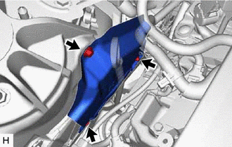
Remove the 3 bolts and front apron fender insulator RH.
-
-
DISCONNECT RELAY BLOCK
-
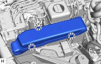
Detach the 3 claws and remove the No. 2 relay block cover.
-
Remove the bolt.
-
Detach the 2 claws and disconnect the wirering harness protector.
-
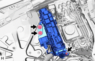
Remove the 2 bolts, nut and disconnect the relay block.
-
Remove the bolt and disconnect the wire harness clamp.
-
Remove the bolt and wire harness clamp bracket.
-
Detach the 9 claws and remove the relay block lower cover.
-
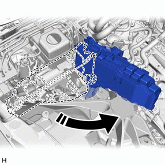
Move the relay block as shown in the illustration to create a clearance.
-
-
DISCONNECT WIRE HARNESS
-
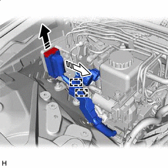

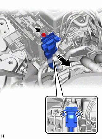
Lock Lever Released 
Connector Disconnected Release the lock lever and disconnect the brake actuator connector from the brake actuator assembly.
-
Detach the 2 clips from the brake actuator bracket assembly.
-
-
DISCONNECT BRAKE TUBE
-
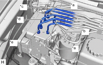
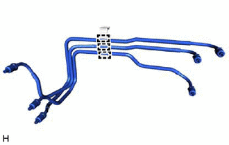
*a From Brake Stroke Simulator Cylinder Sub-assembly *b From Brake Master Cylinder Sub-assembly *c To Rear Wheel Cylinder Assembly RH *d To Rear Wheel Cylinder Assembly LH *e To Front Wheel Cylinder Assembly LH Use tags or make a memo to identify the places to reconnect the brake lines.
-
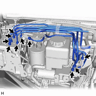
Using a union nut wrench, disconnect the 10 brake tube flare nuts.
Note
-
Do not kink or damage the brake tube.
-
Do not allow any foreign matter such as dirt or dust to enter the brake tube from the connecting parts.
-
-
Remove the bolt and disconnect the No. 2 brake actuator tube clamp.
-
-
REMOVE BRAKE TUBE
-
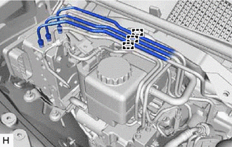
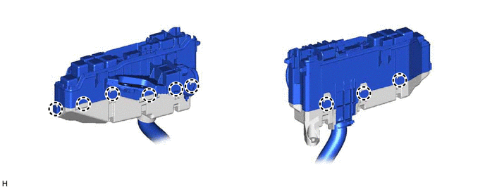
Detach the claws and disconnect the 3 upper side brake tubes from the clamp.
-
Remove the 3 lower side brake tubes with the clamp attached.
-
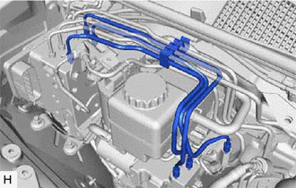
Detach the claws and disconnect the 3 brake tubes from the clamp.
-
-
REMOVE BRAKE ACTUATOR WITH BRACKET
-
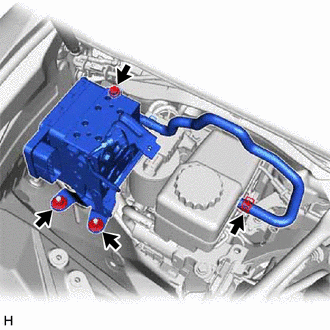
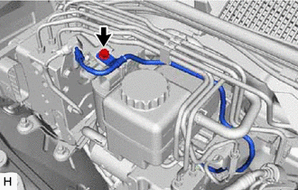
Slide the clip and disconnect the brake actuator hose from the brake master cylinder reservoir assembly.
-
Remove the bolt, 2 nuts and brake actuator with bracket.
Note
-
Do not kink or damage the brake tubes.
-
Do not hold the brake actuator with bracket by the connector, hose or union.
-
Do not allow any foreign matter such as dirt or dust to enter the brake lines from the connecting parts.
-
-
-
REMOVE BRAKE ACTUATOR HOSE
-
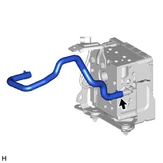
Slide the clip and disconnect the brake actuator hose from the brake actuator assembly.
-
-
REMOVE NO. 3 BRAKE ACTUATOR TUBE
-
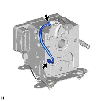
Using a union nut wrench, disconnect the No. 3 brake actuator tube from the brake actuator assembly.
Note
-
Do not kink or damage the No. 3 brake actuator tube.
-
Do not allow any foreign matter such as dirt or dust to enter the No. 3 brake actuator tube from the connecting parts.
-
-
-
REMOVE NO. 1 BRAKE ACTUATOR WAY
-
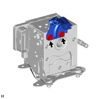
Remove the 2 bolts and No. 1 brake actuator way from the brake actuator assembly.
-
-
REMOVE NO. 2 BRAKE ACTUATOR BRACKET
-
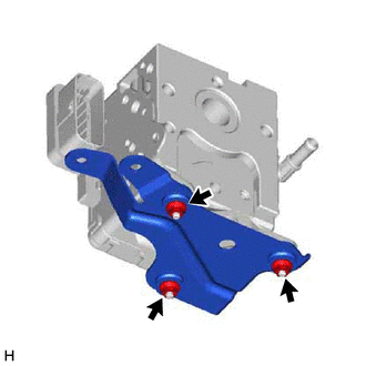
Remove the 3 nuts and No. 2 brake actuator bracket from the brake actuator assembly.
-
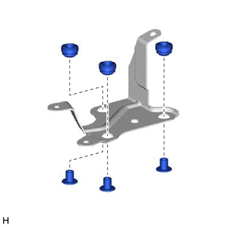
Remove the 3 brake actuator bracket spacers from the brake actuator bracket cushion.
-
Remove the 3 brake actuator bracket cushions from the No. 2 brake actuator bracket.
-
-
REMOVE NO. 1 BRAKE ACTUATOR BRACKET
-
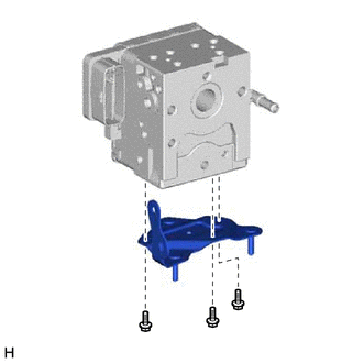
Remove the 3 bolts and No. 1 brake actuator bracket from the brake actuator assembly.
-
-
REMOVE NO. 3 BRAKE ACTUATOR BRACKET
-
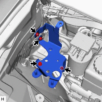
Remove the 4 bolts and No. 3 brake actuator bracket from the body.
-