ELECTRONICALLY CONTROLLED BRAKE SYSTEM, Diagnostic DTC:C1231/31
| DTC Code | DTC Name |
|---|---|
| C1231/31 | Steering Angle Sensor Circuit Malfunction |
DESCRIPTION
The skid control ECU assembly receives steering sensor signals via CAN communication. When a communication malfunction between the skid control ECU and steering sensor occurs, DTC U0126/63 (Lost Communication with Steering Sensor Module) is stored.
| DTC No. | Detection Item | INF Code | DTC Detection Condition | Trouble Area | Note |
|---|---|---|---|---|---|
| C1231/31 | Steering Angle Sensor Circuit Malfunction | 341 342 344 |
|
|
VSC DTC |
| DTC No. | Brake warning light / yellow (minor malfunction) code | ABS warning light code | Slip indicator light code | Brake hold standby indicator light code |
|---|---|---|---|---|
| C1231 | - | - | 31 | - |
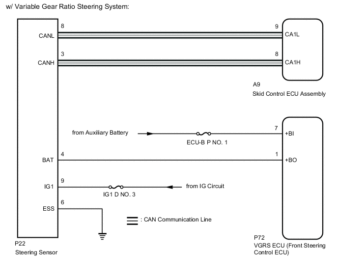
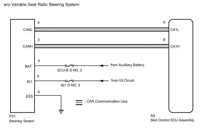
WIRING DIAGRAM
CAUTION / NOTICE / HINT
Note
Inspect the fuses for circuits related to this system before performing the following procedure.
Tech Tips
-
When U0126/63 is output together with C1231/31, inspect and repair the trouble areas indicated by U0126/63 first.
-
When a speed sensor or yaw rate sensor is malfunctioning, DTCs for the steering sensor may be output even when the steering sensor is normal. When DTCs for a speed sensor or the yaw rate sensor are output together with DTCs for the steering sensor, inspect and repair the speed sensor and yaw rate sensor first, and then inspect and repair the steering sensor.
PROCEDURE
-
CHECK DTC
-
Clear the DTCs.
Chassis > ABS/VSC/TRC > Clear DTCs -
Turn the power switch off.
-
Turn the power switch on (IG) again and check that no CAN communication system DTCs are output.
-
Drive the vehicle at a speed of 35 km/h (22 mph), turn the steering wheel to the right and left, and check that no speed sensor and/or yaw rate sensor DTCs are output.
Chassis > ABS/VSC/TRC > Trouble CodesResult Result Proceed to DTC C1231/31 is output. A CAN communication system DTCs are output. B Speed sensor and/or yaw rate sensor DTCs are output. C DTC C1231/31 is not output. D Tech Tips
-
When CAN communication system DTCs are output, repair the CAN communication system before repairing each corresponding sensor.
-
If there is a malfunction in a speed sensor or the yaw rate sensor, an abnormal value may be output even though the steering sensor is normal.
-
If speed sensor and yaw rate sensor DTCs are output simultaneously, repair these malfunctions and inspect the steering sensor.
-
B 
INSPECT CAN COMMUNICATION SYSTEM Click here
C
REPAIR CIRCUITS INDICATED BY OUTPUT DTCS Click here
D
USE SIMULATION METHOD TO CHECK Click here
A 
-
-
CHECK HARNESS AND CONNECTOR (POWER SOURCE TERMINAL)
-
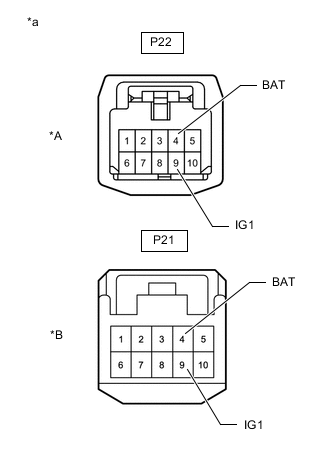
*A w/ Variable Gear Ratio Steering System *B w/o Variable Gear Ratio Steering System *a Front view of wire harness connector
(to Steering Sensor)
Turn the power switch off.
-
Remove the steering wheel and column cover.
-
Make sure that there is no looseness at the locking part and the connecting part of the connector.
-
Disconnect the P21*1 or P22*2 steering sensor connector.
*1: w/o Variable Gear Ratio Steering System
*2: w/ Variable Gear Ratio Steering System
-
Measure the voltage according to the value(s) in the table below.
Standard Voltage w/o Variable Gear Ratio Steering System Tester Connection Condition Specified Condition P21-9 (IG1) - Body ground Power switch on (IG) 11 to 14 V P21-4 (BAT) - Body ground Always 11 to 14 V w/ Variable Gear Ratio Steering System Tester Connection Condition Specified Condition P22-9 (IG1) - Body ground Power switch on (IG) 11 to 14 V P22-4 (BAT) - Body ground Always 11 to 14 V Result Proceed to OK NG
NG
REPAIR OR REPLACE HARNESS OR CONNECTOR (POWER SOURCE CIRCUIT)
OK
-
-
CHECK HARNESS AND CONNECTOR (GROUND TERMINAL)
-
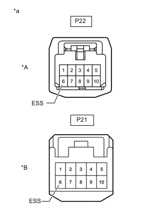
*A w/ Variable Gear Ratio Steering System *B w/o Variable Gear Ratio Steering System *a Front view of wire harness connector
(to Steering Sensor)
Turn the power switch off.
-
Measure the resistance according to the value(s) in the table below.
Note
Before measuring the resistance of the steering sensor, turn the power switch off and leave the vehicle for 1 minute or more without operating the key or switches, or opening or closing the doors.
Standard Resistance w/o Variable Gear Ratio Steering System Tester Connection Condition Specified Condition P21-6 (ESS) - Body ground 1 minute after power switch off Below 1 Ω w/ Variable Gear Ratio Steering System Tester Connection Condition Specified Condition P22-6 (ESS) - Body ground 1 minute after power switch off Below 1 Ω Result Proceed to OK NG (w/o Variable Gear Ratio Steering System) NG (w/ Variable Gear Ratio Steering System)
OK
REPLACE STEERING SENSOR Click here
NG (w/o Variable Gear Ratio Steering System)
REPAIR OR REPLACE HARNESS OR CONNECTOR (GROUND CIRCUIT)
NG (w/ Variable Gear Ratio Steering System)
-
-
CHECK HARNESS AND CONNECTOR (VGRS ECU (FRONT STEERING CONTROL ECU) - STEERING SENSOR)
-
Disconnect the P72 VGRS ECU (front steering control ECU) connector.
-
Measure the resistance according to the value(s) in the table below.
Standard Resistance Tester Connection Condition Specified Condition P72-1 (+BO) - P22-4 (BAT) Always Below 1 Ω P72-1 (+BO) or P22-4 (BAT) - Body ground Always 10 kΩ or higher Result Proceed to OK NG
NG
REPAIR OR REPLACE HARNESS OR CONNECTOR
OK
-
-
CHECK HARNESS AND CONNECTOR (VGRS ECU (FRONT STEERING CONTROL ECU))
-
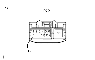
*a Front view of wire harness connector
(to VGRS ECU (Front Steering Control ECU))
Measure the voltage according to the value(s) in the table below.
Standard Voltage Tester Connection Condition Specified Condition P72-7 (+BI) - Body ground Always 11 to 14 V Result Proceed to OK NG
OK
REPLACE VGRS ECU (FRONT STEERING CONTROL ECU) Click here
NG
REPAIR OR REPLACE HARNESS OR CONNECTOR
-