ELECTRONICALLY CONTROLLED BRAKE SYSTEM, Diagnostic DTC:C1381/97
| DTC Code | DTC Name |
|---|---|
| C1381/97 | Acceleration Sensor Power Supply Voltage Malfunction |
DESCRIPTION
This DTC is stored when the skid control ECU assembly receives a sensor supply voltage malfunction signal from the yaw rate sensor.
| DTC No. | Detection Item | INF Code | DTC Detection Condition | Trouble Area | Note |
|---|---|---|---|---|---|
| C1381/97 | Acceleration Sensor Power Supply Voltage Malfunction | 315 | At a vehicle speed of 3 km/h (2 mph) or more, a supply voltage malfunction signal is received from the sensor for 10 seconds or more. |
|
ABS DTC |
| DTC No. | Brake warning light / yellow (minor malfunction) code | ABS warning light code | Slip indicator light code | Brake hold standby indicator light code |
|---|---|---|---|---|
| C1381 | 36 | 97 | 43 | 21 |
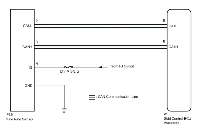
WIRING DIAGRAM
CAUTION / NOTICE / HINT
Note
-
When replacing the yaw rate sensor, perform initialization and calibration of the linear solenoid valve.
-
Inspect the fuses for circuits related to this system before performing the following procedure.
PROCEDURE
-
CHECK HARNESS AND CONNECTOR (IG TERMINAL)
-
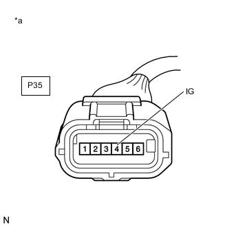
*a Front view of wire harness connector
(to Yaw Rate Sensor)
Make sure that there is no looseness at the locking part and the connecting part of the connector.
-
Disconnect the P35 yaw rate sensor connector.
-
Turn the power switch on (IG).
-
Measure the voltage according to the value(s) in the table below.
Standard Voltage Tester Connection Condition Specified Condition P35-4 (IG) - Body ground Power switch on (IG) 11 to 14 V Result Proceed to OK NG
NG 
REPAIR OR REPLACE HARNESS OR CONNECTOR (IG CIRCUIT)
OK 
-
-
CHECK HARNESS AND CONNECTOR (GND TERMINAL)
-
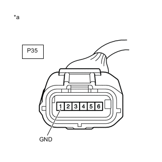
*a Front view of wire harness connector
(to Yaw Rate Sensor)
Turn the power switch off.
-
Measure the resistance according to the value(s) in the table below.
Standard Resistance Tester Connection Condition Specified Condition P35-1 (GND) - Body ground Always Below 1 Ω Result Proceed to OK NG
NG
REPAIR OR REPLACE HARNESS OR CONNECTOR (GND CIRCUIT)
OK
-
-
RECONFIRM DTC
-
Reconnect the P35 yaw rate sensor connector.
-
Clear the DTCs.
Chassis > ABS/VSC/TRC > Clear DTCs -
Turn the power switch off.
-
Turn the power switch on (READY).
-
Perform a road test.
-
Check if the same DTC is output.
Chassis > ABS/VSC/TRC > Trouble CodesResult Result Proceed to DTC C1381/97 is not output. A DTC C1381/97 is output. B
A
USE SIMULATION METHOD TO CHECK Click here
B
REPLACE YAW RATE SENSOR Click here
-