ELECTRONICALLY CONTROLLED BRAKE SYSTEM, Diagnostic DTC:C1377/43
| DTC Code | DTC Name |
|---|---|
| C1377/43 | Capacitor Malfunction |
DESCRIPTION
The brake control power supply with bracket assembly is used as auxiliary power for brake control when the auxiliary battery voltage is low.
| DTC No. | Detection Item | INF Code | DTC Detection Condition | Trouble Area | Note |
|---|---|---|---|---|---|
| C1377/43 | Capacitor Malfunction | 101 102 103 105 106 108 109 110 |
|
|
Electronically controlled brake system DTC |
| DTC No. | Brake warning light / yellow (minor malfunction) code | ABS warning light code | Slip indicator light code | Brake hold standby indicator light code |
|---|---|---|---|---|
| C1377 | 43 | - | - | - |
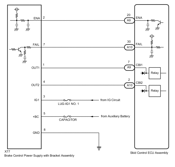
WIRING DIAGRAM
CAUTION / NOTICE / HINT
Note
-
When replacing the skid control ECU assembly, perform initialization and calibration of the linear solenoid valve.
-
Inspect the fuses for circuits related to this system before performing the following procedure.
PROCEDURE
-
CHECK FREEZE FRAME DATA
-
Check the INF code from the Freeze Frame Data stored when DTC (C1377/43) was stored.
Result Result Proceed to INF codes 109 and/or 110 are output. A INF codes 101, 102, 105, 106 and/or 108 are output. B INF code 103 is output. C
B 
REPLACE BRAKE CONTROL POWER SUPPLY WITH BRACKET ASSEMBLY Click here
C 
CHECK AUXILIARY BATTERY Click here
A 
-
-
CHECK HARNESS AND CONNECTOR (+BC TERMINAL)
-
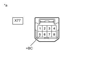
*a Front view of wire harness connector
(to Brake Control Power Supply with Bracket Assembly)
Make sure that there is no looseness at the locking part and the connecting part of the connector.
-
Disconnect the X77 brake control power supply with bracket assembly connector.
-
Measure the voltage according to the value(s) in the table below.
Standard Voltage Tester Connection Condition Specified Condition X77-5 (+BC) - Body ground Always 11 to 14 V Result Proceed to OK NG
NG
REPAIR OR REPLACE HARNESS OR CONNECTOR (+BC CIRCUIT)
OK
-
-
CHECK HARNESS AND CONNECTOR (GND TERMINAL)
-
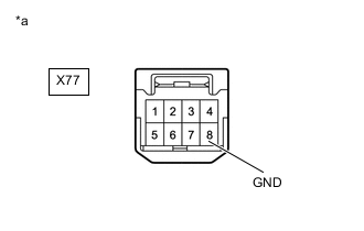
*a Front view of wire harness connector
(to Brake Control Power Supply with Bracket Assembly)
Measure the resistance according to the value(s) in the table below.
Standard Resistance Tester Connection Condition Specified Condition X77-8 (GND) - Body ground Always Below 1 Ω Result Proceed to OK NG
NG
REPAIR OR REPLACE HARNESS OR CONNECTOR (GND CIRCUIT)
OK
-
-
INSPECT BRAKE CONTROL POWER SUPPLY WITH BRACKET ASSEMBLY (BRAKE CONTROL POWER SUPPLY WITH BRACKET ASSEMBLY POWER SUPPLY OUTPUT)
-
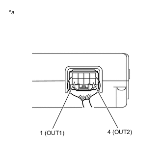
*a Component with harness connected
(Brake Control Power Supply with Bracket Assembly)
Reconnect the X77 brake control power supply with bracket assembly connector.
-
Turn the power switch on (IG).
-
Measure the voltage according to the value(s) in the table below.
Standard Voltage Tester Connection Condition Specified Condition 1 (OUT1) - Body ground Power switch on (IG) 11 to 14 V 4 (OUT2) - Body ground Power switch on (IG) 11 to 14 V Result Proceed to OK NG
NG
REPLACE BRAKE CONTROL POWER SUPPLY WITH BRACKET ASSEMBLY Click here
OK
-
-
INSPECT SKID CONTROL ECU ASSEMBLY (BRAKE CONTROL POWER SUPPLY WITH BRACKET ASSEMBLY POWER SUPPLY INPUT)
-
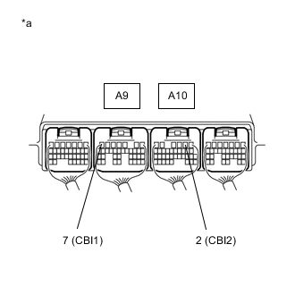
*a Component with harness connected
(Skid Control ECU Assembly)
Turn the power switch on (IG).
-
Measure the voltage according to the value(s) in the table below.
Standard Voltage Tester Connection Condition Specified Condition A9-7 (CBI1) - Body ground Power switch on (IG) 8.8 to 14 V A10-2 (CBI2) - Body ground Power switch on (IG) 8.8 to 14 V Result Proceed to OK NG
NG
REPLACE SKID CONTROL ECU ASSEMBLY for RHD: Click here
REPLACE SKID CONTROL ECU ASSEMBLY for LHD: Click hereOK
-
-
RECONFIRM DTC
-
Turn the power switch off.
-
Clear the DTCs.
Chassis > ABS/VSC/TRC > Clear DTCs -
Turn the power switch off.
-
Turn the power switch on (IG).
-
Check if the same DTC is output.
Chassis > ABS/VSC/TRC > Trouble CodesResult Result Proceed to DTC C1377/43 is not output. A DTC C1377/43 is output. B
A
USE SIMULATION METHOD TO CHECK Click here
B
REPLACE SKID CONTROL ECU ASSEMBLY for RHD: Click here
REPLACE SKID CONTROL ECU ASSEMBLY for LHD: Click here -
-
CHECK AUXILIARY BATTERY
-
Check the auxiliary battery voltage.
Standard Voltage Tester Connection Condition Specified Condition Auxiliary battery Power switch on (IG) 11 to 14 V Auxiliary battery Power switch on (READY) 11 to 15.5 V Result Proceed to OK NG
NG
CHARGE OR REPLACE AUXILIARY BATTERY
OK
-
-
CHECK HARNESS AND CONNECTOR (+BC TERMINAL)
-
*a Front view of wire harness connector
(to Brake Control Power Supply with Bracket Assembly)
Make sure that there is no looseness at the locking part and the connecting part of the connector.
-
Disconnect the X77 brake control power supply with bracket assembly connector.
-
Measure the voltage according to the value(s) in the table below.
Standard Voltage Tester Connection Condition Specified Condition X77-5 (+BC) - Body ground Always 11 to 14 V Result Proceed to OK NG
NG
REPAIR OR REPLACE HARNESS OR CONNECTOR (+BC CIRCUIT)
OK
-
-
CHECK HARNESS AND CONNECTOR (GND TERMINAL)
-
*a Front view of wire harness connector
(to Brake Control Power Supply with Bracket Assembly)
Measure the resistance according to the value(s) in the table below.
Standard Resistance Tester Connection Condition Specified Condition X77-8 (GND) - Body ground Always Below 1 Ω Result Proceed to OK NG
OK
REPLACE BRAKE CONTROL POWER SUPPLY WITH BRACKET ASSEMBLY Click here
NG
REPAIR OR REPLACE HARNESS OR CONNECTOR (GND CIRCUIT)
-