REAR UPPER ARM REMOVAL

CAUTION / NOTICE / HINT
The necessary procedures (adjustment, calibration, initialization, or registration) that must be performed after parts are removed, installed, or replaced during the rear upper arm removal/installation are shown below.
| Necessary Procedure After Parts Removed/Installed/Replaced | ||||||||||||
|---|---|---|---|---|---|---|---|---|---|---|---|---|
|
*1: The vehicle height changes due to suspension or tire replacement.
Tech Tips
-
Use the same procedure for the RH and LH sides.
-
The procedure listed below is for the LH side.
PROCEDURE
-
REMOVE REAR WHEEL
-
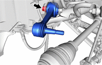
REMOVE REAR NO. 1 SUSPENSION ARM ASSEMBLY LH
-
Remove the nut.
-
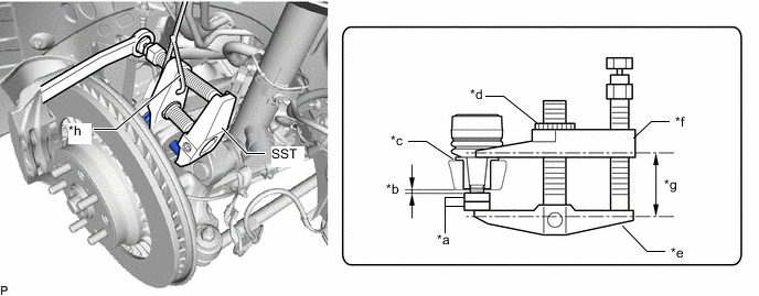
Install 2 SST (spacer A) onto the rear No. 1 suspension arm assembly LH so that there is a space of approximately 1 mm (0.0394 in.) between the arm and spacers.
- SST
- 09960-20010 ( 09961-02050 )
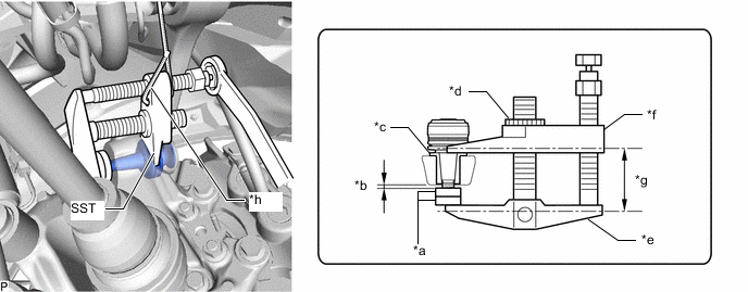
*a SST (Spacer A) *b 1 mm (0.0394 in.) *c Spacer *d Center Nut *e Body *f Claw *g Parallel *h String Note
-
Make sure to install the spacers (SST spacer A) as the rear axle carrier sub-assembly LH spacer may shift.
-
As SST may become damaged, make sure the space between the arm and spacers is not 1 mm (0.0394 in.) or less.
-
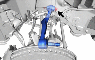
Using SST, disconnect the rear No. 1 suspension arm assembly LH from the rear axle carrier sub-assembly LH.
- SST
- 09960-20010 ( 09961-02010 )
Note
-
Apply molybdenum grease to the bolt threads and end of the SST bolt.
-
Do not damage the dust cover.
-
As the dust cover may be damaged, adjust SST with the center nut so that the body and claw are parallel.
-
Make sure to tie the string of SST to the vehicle to prevent SST from dropping.
-
Remove the nut, washer, bolt and rear No. 1 suspension arm assembly LH from the rear suspension member sub-assembly.
-
-
REMOVE REAR SHOCK ABSORBER WITH COIL SPRING LH
-
REMOVE REAR SHOCK ABSORBER WITH COIL SPRING RH
Tech Tips
Perform the same procedure as for the LH side.
-
REMOVE PROPELLER SHAFT ASSEMBLY
-
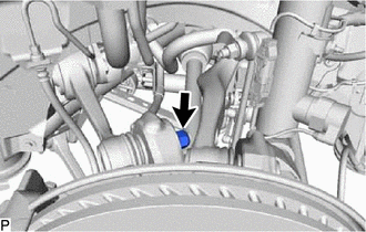
DISCONNECT REAR UPPER CONTROL ARM ASSEMBLY LH
-
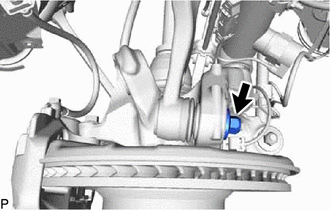
Remove the nut.
-
Install 2 SST (spacer A) onto the rear upper control arm assembly LH so that there is a space of approximately 1 mm (0.0394 in.) between the arm and spacers.
- SST
- 09960-20010 ( 09961-02050 )
*a SST (Spacer A) *b 1 mm (0.0394 in.) *c Spacer *d Center Nut *e Body *f Claw *g Parallel *h String Note
-
Make sure to install the spacers (SST spacer A) as the rear axle carrier sub-assembly LH spacer may shift.
-
As SST may become damaged, make sure the space between the arm and spacers is not 1 mm (0.0394 in.) or less.
-
Using SST, disconnect the rear upper control arm assembly LH from the rear axle carrier sub-assembly LH.
- SST
- 09960-20010 ( 09961-02010 )
Note
-
Apply molybdenum grease to the bolt threads and end of the SST bolt.
-
Do not damage the dust cover.
-
As the dust cover may be damaged, adjust SST with the center nut so that the body and claw are parallel.
-
Make sure to tie the string of SST to the vehicle to prevent SST from dropping.
-
Loosen the bolt.
Note
Because the nut has its own stopper, do not turn the nut. Loosen the bolt with the nut secured.
-
-
DISCONNECT REAR SUSPENSION MEMBER SUB-ASSEMBLY
-
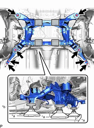
*a Attachment *b Engine Lifter 
Attachment placement location Support the rear suspension member sub-assembly with an engine lifter using 4 attachments or equivalent tools as shown in the illustration.
CAUTION:
-
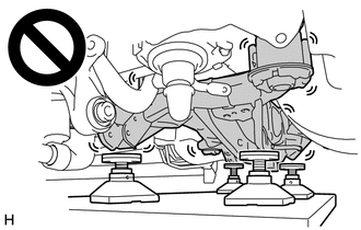
The rear suspension member sub-assembly is a very heavy component. Make sure that it is supported securely.
-
If the rear suspension member sub-assembly is not securely supported, it may drop, resulting in serious injury.
Note
Use attachments to keep the rear suspension member sub-assembly level.
-
-
Remove the 8 bolts, rear lower suspension member stopper LH, rear lower suspension member stopper RH, rear lower suspension member stopper and rear suspension member sub-assembly.
-
Gradually lower the universal engine lifter until it reaches a position where the bolt of the rear upper control arm assembly LH can be removed and disconnect the rear suspension member sub-assembly.
Note
-
When lowering the rear suspension member sub-assembly, be careful not to damage the vehicle body or other components installed to the vehicle.
-
Check that the brake hose and wire harness are not stretched before performing this procedure.
-
-
-
REMOVE REAR UPPER CONTROL ARM ASSEMBLY LH
-
Remove the bolt, nut and rear upper control arm assembly LH.
-