REAR LOWER ARM REMOVAL

CAUTION / NOTICE / HINT
The necessary procedures (adjustment, calibration, initialization, or registration) that must be performed after parts are removed, installed, or replaced during the rear lower arm removal/installation are shown below.
| Necessary Procedure After Parts Removed/Installed/Replaced | ||||||||||||
|---|---|---|---|---|---|---|---|---|---|---|---|---|
|
*1: The vehicle height changes due to suspension or tire replacement.
Tech Tips
-
Use the same procedure for the RH and LH sides.
-
The procedure listed below is for the LH side.
PROCEDURE
-
REMOVE REAR WHEEL
-
REMOVE NO. 2 DIFFERENTIAL SUPPORT PROTECTOR
-
REMOVE LOWER CONTROL ARM ASSEMBLY LH
-
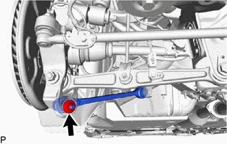
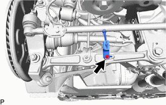
Remove the nut.
-
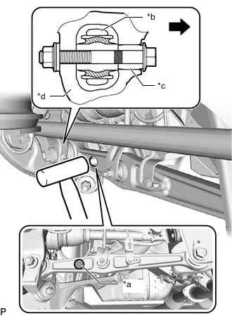
Install 2 SST (spacer B) onto the lower control arm assembly LH so that there is a space of approximately 1 mm (0.0394 in.) between the arm and spacers.
- SST
- 09960-20010 ( 09961-02060 )
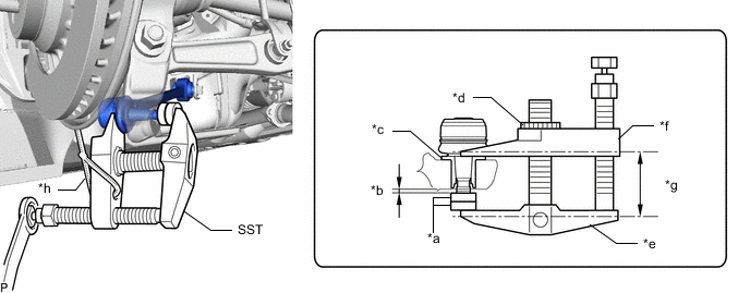
*a SST (Spacer B) *b 1 mm (0.0394 in.) *c Spacer *d Center Nut *e Body *f Claw *g Parallel *h String Note
-
Make sure to install the spacers (SST spacer A) as the rear axle carrier sub-assembly LH spacer may shift.
-
As SST may become damaged, make sure the space between the arm and spacers is not 1 mm (0.0394 in.) or less.
-
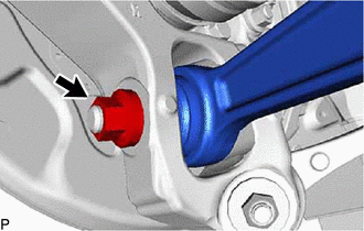
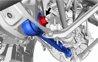
Using SST, disconnect the lower control arm assembly LH from the rear axle carrier sub-assembly LH.
- SST
- 09960-20010 ( 09961-02010 )
Note
-
Apply molybdenum grease to the bolt threads and end of the SST bolt.
-
Do not damage the dust cover.
-
As the dust cover may be damaged, adjust SST with the center nut so that the body and claw are parallel.
-
Make sure to tie the string of SST to the vehicle to prevent SST from dropping.
-
Remove the bolt, nut and lower control arm assembly LH.
Note
Because the nut has its own stopper, do not turn the nut. Loosen the bolt with the nut secured.
-
-
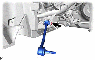
DISCONNECT REAR STABILIZER LINK ASSEMBLY LH
-
Remove the bolt and nut, disconnect rear stabilizer link assembly LH from the rear No. 2 suspension arm assembly LH.
-
-
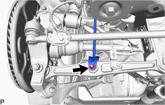
DISCONNECT REAR HEIGHT CONTROL SENSOR SUB-ASSEMBLY LH
-
Remove the bolt and disconnect rear height control sensor sub-assembly LH from the rear No. 2 suspension arm assembly LH.
-
-
REMOVE REAR NO. 2 SUSPENSION ARM ASSEMBLY LH
-
*a A *b Arm *c Slide Pin *d Axle Carrier 
Front of the Vehicle Using a plastic-faced hammer or equivalent, strike the part labeled A from the rear of the vehicle to maintain the clearance at the slide pin area.
Note
Be careful not to damage the arm.
-
Remove the nut, bolt and washer.
-
Remove the nut, rear No. 2 suspension toe adjust plate, rear suspension arm attachment sub-assembly and rear No. 2 suspension arm assembly LH.
-