REAR WHEEL ALIGNMENT ADJUSTMENT
CAUTION / NOTICE / HINT
The necessary procedures (adjustment, calibration, initialization, or registration) that must be performed after completing the rear wheel alignment procedure are shown below.
| Replacement Part or Procedure | Necessary Procedures | Effects/Inoperative when not Performed | Link |
|---|---|---|---|
| Rear steering link assembly or rear suspension have been removed/installed, replaced, or adjusted |
|
Steering wheel off-center | |
| Suspension, tires, etc*1 | Television camera assembly optical axis (Back camera position setting) | Parking assist monitor system |
*1: The vehicle height changes due to suspension or tire replacement.
PROCEDURE
-
INSPECT TIRES
-
MEASURE VEHICLE HEIGHT
-
INSPECT CAMBER
Note
Inspect while the vehicle is unloaded.
-
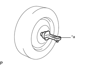
*a Camber-caster-kingpin Gauge Install a camber-caster-kingpin gauge.
-
Inspect the camber.
Camber (Unloaded Vehicle) Camber Inclination Right-left Difference -1°20' +/- 0°45' (-1.33° +/- 0.75°) 0°45' (0.75°) or less Tech Tips
Camber is not adjustable. If the measurement is not within the specified range, inspect the suspension parts for damage and/or wear, and replace them if necessary.
-
-
INSPECT TOE-IN
Note
Inspect while the vehicle is unloaded.
-
Bounce the vehicle up and down at the corners to stabilize the suspension.
-
Release the parking brake and move the shift lever to N.
-
Push the vehicle straight ahead approximately 5.0 m (16.4 ft.). (Step A)
-
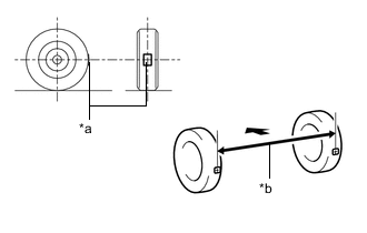
*a Tread Center Mark *b Dimension B 
Front of the Vehicle Put tread center marks on the rearmost points of the rear wheels and measure the distance between the marks (dimension B).
-
Slowly push the vehicle straight ahead to cause the rear wheels to rotate 180°. Use the rear tire valve as a reference point.
Tech Tips
Do not allow the wheels to rotate more than 180°. If the wheels rotate more than 180°, perform the procedure from step A again.
-
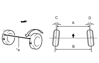
*a Dimension A Front of the Vehicle Measure the distance between the tread center marks on the front of the rear wheels (dimension A).
Toe-in (Unloaded Vehicle) Vehicle Specification Specified Condition w/o Dynamic Rear Steering C + D: 0°14' +/- 0°09' (0.23° +/- 0.15°)
B - A: 3.0 +/- 2.0 mm (0.1181 +/- 0.0787 in.)
w/ Dynamic Rear Steering Tire Size: 245/45RF20 C + D: 0°14' +/- 0°09' (0.23° +/- 0.15°)
B - A: 3.0 +/- 2.0 mm (0.1181 +/- 0.0787 in.)
Tire Size: 275/35RF21 for Korea C + D: 0°00' +/- 0°09' (0.00° +/- 0.15°)
B - A: 0.0 +/- 2.0 mm (0.0000 +/- 0.0787 in.)
except Korea C + D: 0°14' +/- 0°09' (0.23° +/- 0.15°)
B - A: 3.0 +/- 2.0 mm (0.1181 +/- 0.0787 in.)
Tech Tips
Measure "B - A" only when "C + D" cannot be measured.
If the toe-in is not within the specified range, adjust it at the toe control link sub-assembly.
-
-
ADJUST TOE-IN (w/o Dynamic Rear Steering)
-
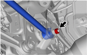
Loosen the nut of the toe control link sub-assembly (on the rear suspension member sub-assembly side).
Note
Hold the toe adjust cam sub-assembly while rotating the nut.
-
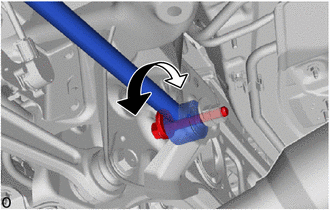
Rotate the toe adjust cam sub-assembly to adjust the toe-in.
Toe-in (Unloaded Vehicle) Specified Condition C + D: 0°14' +/- 0°09' (0.23° +/- 0.15°) B - A: 3.0 +/- 2.0 mm (0.1181 +/- 0.0787 in.) Tech Tips
-
Perform adjustments so that the value is as close as possible to the median of the specified range.
-
Rotating the toe adjust cam sub-assembly by one notch changes the toe by approximately 4.6 mm (0.181 in.).
-
-
Tighten the nut of the toe control link sub-assembly (on the rear suspension member sub-assembly side).
- Torque:
- 78 N*m { 795 kgf*cm, 58 ft.*lbf }
Note
Hold the toe adjust cam sub-assembly while rotating the nut.
-
-
ADJUST TOE-IN (w/ Dynamic Rear Steering)
Note
If any underbody rear suspension parts are removed and installed, replaced or adjusted, the steering wheel may become off center.
Therefore, perform neutral point memorization and motor rotation angle sensor calibration.
-
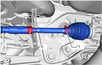
*1 Steering Rack Boot Clip *2 Lock Nut Make sure that the thread length of the right and left steering rack ends are approximately the same.
Standard Difference 1.5 mm (0.0591 in.) or less -
Remove the steering rack boot clips.
-
Loosen the tie rod assembly lock nuts.
-
Adjust the steering rack ends if the difference in thread length between the right and left steering rack ends is not within the specified range.
-
If the toe-in measurement is greater than the specified range (too much toe-in), shorten the longer steering rack end so that the length difference is within the specified range.
-
If the toe-in measurement is less than the specified range (too much toe-out), lengthen the shorter steering rack end so that the length difference is within the specified range.
-
Measure the toe-in.
-
-
Turn the right and left steering rack ends by an equal amount to adjust the toe-in.
Toe-in (Unloaded Vehicle) Vehicle Specification Specified Condition Tire Size: 245/45RF20 C + D: 0°14' +/- 0°09' (0.23° +/- 0.15°)
B - A: 3.0 +/- 2.0 mm (0.1181 +/- 0.0787 in.)
Tire Size: 275/35RF21 for Korea C + D: 0°00' +/- 0°09' (0.00° +/- 0.15°)
B - A: 0.0 +/- 2.0 mm (0.0000 +/- 0.0787 in.)
except Korea C + D: 0°14' +/- 0°09' (0.23° +/- 0.15°)
B - A: 3.0 +/- 2.0 mm (0.1181 +/- 0.0787 in.)
Tech Tips
Perform adjustments so that the value is as close as possible to the median of the specified range.
-
Make sure that the thread length of the right and left steering rack ends are the same.
-
Tighten the tie rod assembly lock nuts.
- Torque:
- 55 N*m { 561 kgf*cm, 41 ft.*lbf }
Note
Temporarily tighten the lock nut while holding the hexagonal part of the steering rack end so that the lock nut and the steering rack end do not turn together.
Hold the width across flat of the tie rod end and tighten the lock nut.
-
Place the steering rack boots on the seats and install the steering rack boot clips.
Tech Tips
-
Make sure that the steering rack boots are not twisted.
-
Make sure that the steering rack boot clips are facing towards the front of the vehicle.
-
-
Perform neutral position memorization and motor rotation angle sensor calibration for the dynamic rear steering system.
-
-
INSPECT REAR SUSPENSION
-
Inspect the rear suspension member sub-assembly.
-
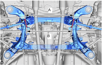
Measure the distance between the centers of the 2 installation bolts of the rear No. 2 suspension arm assembly LH and RH.
Standard Length A 629.5 mm (2.06 ft.) Length B 582.7 mm (1.91 ft.) If the distance is not within the specified range, replace the rear suspension member sub-assembly.
-
Visually inspect the press holes on the installation area of the rear upper No. 2 control arm assembly.
Standard The holes are not deformed. If the holes are deformed, replace the rear suspension member.
-
-
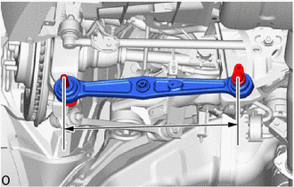
Inspect the lower control arm assembly.
-
Measure the distance between the centers of the 2 installation bolts of the lower control arm assembly.
Standard 357.2 mm (1.17 ft.) If the distance is not within the specified range, replace the lower control arm assembly.
-
-
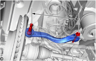
Inspect the rear No. 2 suspension arm assembly.
-
Measure the distance between the centers of the 2 installation bolts of the rear No. 2 suspension arm assembly.
Standard 422.2 mm (1.38 ft.) If the distance is not within the specified range, replace the rear No. 2 suspension arm assembly.
-
-
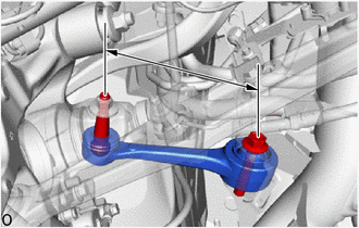
Inspect the rear No. 1 suspension arm assembly.
-
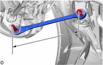
Measure the distance between the center of the rear No. 1 suspension arm assembly installation bolt and the ball joint stud.
Standard 206.0 mm (8.1102 in.) If the distance is not within the specified range, replace the rear No. 1 suspension arm assembly.
-
-
Inspect the rear upper control arm assembly.
-
Measure the distance between the center of the rear upper control arm assembly installation bolt and the ball joint stud.
Standard 324.5 mm (1.06 ft.) If the distance is not within the specified range, replace the rear upper control arm assembly.
-
-
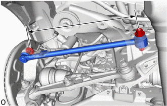
w/o Dynamic Rear Steering:
Inspect the toe control link sub-assembly.
-
Measure the distance between the center of the toe control link sub-assembly installation bolt and the ball joint stud.
Standard 481.0 mm (1.58 ft.) If the distance is not within the specified range, replace the toe control link sub-assembly
-
-
-
REPLACE REAR SUSPENSION ARM ATTACHMENT SUB-ASSEMBLY
-
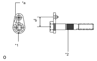
*1 Toe Adjust Plate *2 Rear Suspension Attachment *a Stamping Position *b Dimension A When rear suspension member is not replaced:
-
Use the same stamping No. as the parts that were removed from the left and right side of the vehicle.
-
-
When rear suspension member is replaced:
-
Use stamping A for the parts that were removed from the left and right side of the vehicle.
Part No. information Stamping No. Part No.
Rear Suspension Attachment
Part No.
Toe Adjust Plate
Dimension A A 48709-11020 48452-11010 30 mm (1.1811 in.) B 48709-11030 48452-11020 28 mm (1.1024 in.) C 48709-11040 48452-11030 32 mm (1.2598 in.)
-
-
-
ALIGN FRONT WHEELS FACING STRAIGHT AHEAD
-
PERFORM YAW RATE AND ACCELERATION SENSOR CALIBRATION