REAR AXLE HUB ON-VEHICLE INSPECTION

CAUTION / NOTICE / HINT
The necessary procedures (adjustment, calibration, initialization, or registration) that must be performed after parts are removed, installed, or replaced when performing the rear axle hub inspection are shown below.
| Replacement Part or Procedure | Necessary Procedure | Effect/Inoperative when not Performed | Link |
|---|---|---|---|
|
Parking brake bedding | Electric parking brake system |
Note
-
When the brake pedal is first depressed after replacing the brake pads or pushing back the disc brake piston, DTC C1341, C1342, C1343 and/or C1344 may be stored. As there is no malfunction, clear the DTCs.
-
While the auxiliary battery is connected, even if the power switch is off, the brake control system activates when the brake pedal is depressed or any door courtesy switch is turned on. Therefore, when servicing, do not depress the brake pedal or open/close the doors while the auxiliary battery is connected.
Tech Tips
-
Use the same procedure for the RH side and LH side.
-
The following procedure is for the LH side.
PROCEDURE
-
DISCONNECT BRAKE BOOSTER PUMP CONNECTOR
-
REMOVE REAR WHEEL
-
DISCONNECT REAR DISC BRAKE CYLINDER ASSEMBLY
-
REMOVE PARKING BRAKE SHOE SHOE ADJUSTING HOLE PLUG
-
REMOVE REAR DISC LH
-
INSPECT REAR AXLE HUB BEARING LOOSENESS
-
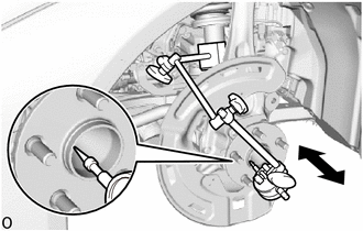
Using a dial indicator, check for looseness near the center of the rear axle hub.
Maximum Looseness 0.05 mm (0.00196 in.) Note
-
Ensure that the dial indicator is set perpendicular to the measurement surface.
-
Keep the magnet of the dial indicator away from the rear axle hub and bearing assembly.
If the looseness exceeds the maximum, replace the rear axle hub and bearing assembly.
-
-
-
INSPECT REAR AXLE HUB RUNOUT
-
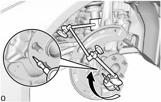
Using a dial indicator, check for runout on the surface of the rear axle hub outside the rear axle hub bolts.
Maximum Runout 0.05 mm (0.00196 in.) Note
-
Ensure that the dial indicator is set perpendicular to the measurement surface.
-
Make sure to install the tip of the dial indicator towards the outside of the rear axle hub bolts.
-
Keep the magnet of the dial indicator away from the rear axle hub and bearing assembly.
If the runout exceeds the maximum, replace the rear axle hub and bearing assembly.
-
-
-
INSTALL REAR DISC LH
-
INSTALL PARKING BRAKE SHOE ADJUSTING HOLE PLUG
-
CONNECT REAR DISC BRAKE CYLINDER ASSEMBLY
-
ADJUST PARKING BRAKE
-
INSTALL REAR WHEEL
-
CONNECT BRAKE BOOSTER PUMP CONNECTOR
-
PERFORM PARKING BRAKE SHOE BEDDING