FRONT AXLE HUB REMOVAL

CAUTION / NOTICE / HINT
The necessary procedures (adjustment, calibration, initialization, or registration) that must be performed after parts are removed, installed, or replaced during the front axle hub removal/installation are shown below.
| Necessary Procedure After Parts Removed/Installed/Replaced | ||||||||||||
|---|---|---|---|---|---|---|---|---|---|---|---|---|
|
*1: The vehicle height changes due to suspension or tire replacement.
CAUTION / NOTICE / HINT
Note
-
When the brake pedal is first depressed after replacing the brake pads or pushing back the disc brake piston, DTC C1341, C1342, C1343 and/or C1344 may be stored. As there is no malfunction, clear the DTCs.
-
While the auxiliary battery is connected, even if the power switch is off, the brake control system activates when the brake pedal is depressed or any door courtesy switch is turned on. Therefore, when servicing, do not depress the brake pedal or open/close the doors while the auxiliary battery is connected.
Tech Tips
-
The following procedure is for the LH side.
-
Other than areas where instructions are provided, use the same procedure for the LH and RH sides.
PROCEDURE
-
DISCONNECT BRAKE BOOSTER PUMP CONNECTOR
-
REMOVE FRONT WHEEL
-
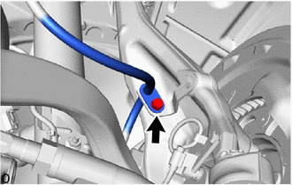
DISCONNECT FRONT SKID CONTROL SENSOR WIRE
-
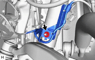
Remove the nut and sensor clamp.
-
for LH side:
-
Disconnect the front skid control sensor wire connector.
-
Remove the bolt and sensor clamp.
-
-
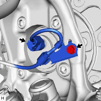
for RH side:
-
Disconnect the pad wear indicator connector.
-
Disconnect the front skid control sensor wire connector.
-
Remove the bolt and sensor clamp.
-
-
-
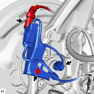
DISCONNECT DISC BRAKE CYLINDER ASSEMBLY
-
for RH side:
-
Detach the guide to remove the pad wear indicator assembly.
-
-
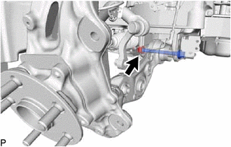
Disconnect the bolt and front flexible hose from front flexible hose bracket LH.
-
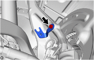
Remove the bolt and front flexible hose bracket LH from steering knuckle LH.
-
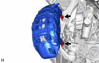
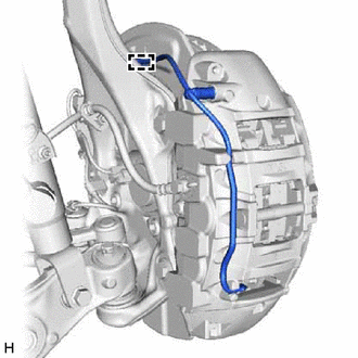
Loosen the bolts on the lower side of the disc brake cylinder assembly LH and remove the bolts on the top side.
Note
Do not excessively loosen the bolts on the lower side of the disc brake cylinder assembly LH.
-
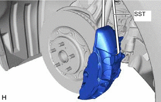
Tilt the disc brake cylinder assembly LH and install SST as shown in the illustration.
- SST
- 09727-00110
-
Install SST to the No. 2 front suspension upper arm assembly LH.
Note
The No. 2 front suspension upper arm assembly LH may become damaged if the metal part of SST contacts it. Therefore, install it so that the metal part does not contact the No. 2 front suspension upper arm assembly LH.
-
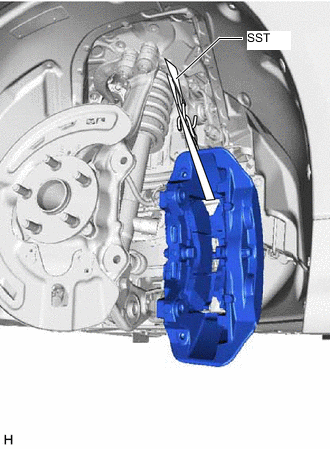
Remove the bolt on the lower side of the disc brake cylinder assembly LH and disconnect it.
Note
-
Do not apply excessive force to the flexible hose.
-
If there is no looseness in the flexible hose, adjust the length of SST.
-
-
-
REMOVE FRONT DISC LH
-
REMOVE FRONT DISC BRAKE DUST COVER LH
-
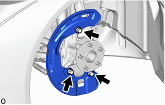
Remove the 3 bolts and front disc brake dust cover LH.
-
-
DISCONNECT TIE ROD ASSEMBLY LH
-
DISCONNECT FRONT LOWER SUSPENSION ARM ASSEMBLY LH
-
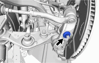
Remove the clip and nut.
-
Install 2 SST (spacer A) onto the front lower suspension arm assembly LH so that there is a space of approximately 1 mm (0.0394 in.) between the arm and spacers.
- SST
- 09960-20010 ( 09961-02050 )
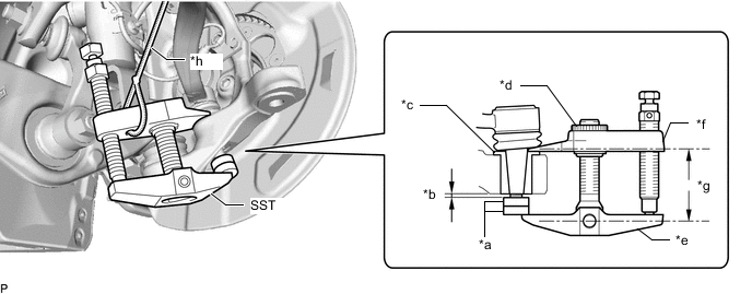
*a SST (Spacer A) *b 1 mm (0.0394 in.) *c Spacer *d Center Nut *e Body *f Claw *g Parallel *h String Note
-
Make sure to install the spacers (SST spacer A) as the steering knuckle spacer may shift.
-
As SST may become damaged, make sure the space between the arm and spacers is not 1 mm (0.0394 in.) or less.
-
Using SST, disconnect the front lower suspension arm assembly LH from the steering knuckle assembly LH.
- SST
- 09960-20010 ( 09961-02010 )
Note
-
Apply molybdenum grease to the bolt threads and end of SST bolt.
-
Do not damage the dust cover.
-
As the dust cover may be damaged, adjust SST with the center nut so that the body and claw are parallel.
-
Make sure to tie the string of SST to the vehicle to prevent SST from dropping.
-
-
REMOVE NO. 2 ENGINE UNDER COVER ASSEMBLY
-
REMOVE ENGINE SIDE COVER LH
-
DISCONNECT FRONT HEIGHT CONTROL SENSOR SUB-ASSEMBLY LH
-
REMOVE REAR LOWER ARM MOUNTING REINFORCEMENT SUB-ASSEMBLY LH
-
DISCONNECT FRONT STABILIZER LINK ASSEMBLY LH
-
DISCONNECT FRONT SHOCK ABSORBER ASSEMBLY LH
-
DISCONNECT LOWER NO. 2 SUSPENSION ARM ASSEMBLY LH
-
Disconnect the bolt, nut and lower No. 2 suspension arm assembly LH.
-
-
DISCONNECT STEERING KNUCKLE LH
-
REMOVE FRONT AXLE HUB SUB-ASSEMBLY LH
-
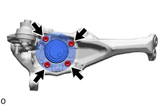
Using a hexagon socket wrench 12 mm, remove the 4 bolts and front axle hub sub-assembly LH.
-
-
REMOVE DISC BRAKE AIR GUIDE PLATE
-
Remove the disc brake air guide plate from the steering knuckle LH.
-