PROPELLER SHAFT ASSEMBLY INSPECTION

PROCEDURE
-
INSPECT FLEXIBLE COUPLING
-
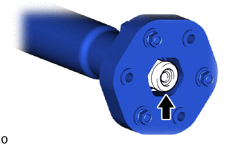
Check the front and rear flexible couplings for cracks or damage.
-
Inspect the flexible coupling centering bushings.
Tech Tips
If a bushing is damaged, replace the propeller with center bearing shaft assembly.
-
-
INSPECT PROPELLER SHAFT ASSEMBLY
-
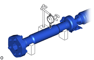
Using a dial indicator, measure the runout of the propeller with center bearing shaft assembly (front side).
Maximum Runout 0.5 mm (0.0196 in.) Note
-
The dial indicator must be set at a right angle to the center of the propeller with center bearing shaft assembly (front side).
-
Make sure the V block does not interfere with the balance piece.
If the shaft runout exceeds the maximum, replace the propeller with center bearing shaft assembly.
-
-
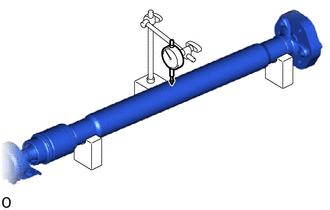
Using a dial indicator, measure the runout of the propeller with center bearing shaft assembly (rear side).
Maximum Runout 0.6 mm (0.0236 in.) Note
-
The dial indicator must be set at a right angle to the center of the propeller with center bearing shaft assembly (rear side).
-
Make sure the V block does not interfere with the balance piece.
If the shaft runout exceeds the maximum, replace the propeller with center bearing shaft assembly.
-
-