REAR DRIVE SHAFT ASSEMBLY INSTALLATION

PROCEDURE
-
INSTALL REAR DRIVE SHAFT ASSEMBLY LH
-
Install a new shaft snap ring.
Note
-
Do not damage the spline of the rear drive inboard joint assembly LH.
-
The shaft snap ring should be installed completely.
-
-
Coat the spline of the rear drive inboard joint assembly with Toyota genuine differential gear oil.
w/ LSD Toyota genuine differential gear oil LX 75W-85 GL-5 or equivalent w/o LSD Toyota genuine differential gear oil LT 75W-85 GL-5 or equivalent -
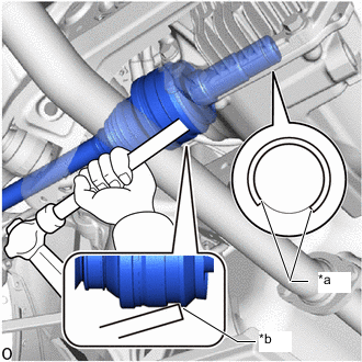
*a Opening Facing *b Press-fit wall Align the inboard joint splines, and using a brass bar and a hammer, install the rear drive shaft assembly LH.
Note
-
Set the shaft snap ring in the groove with the opening facing downwards and centered radially.
-
Do not damage the oil seal, boot and dust cover.
-
Make sure to follow the proper handling and installation procedures. If the rear drive shaft assembly LH is installed at too large an angle or slides too much, it may fall out of the groove of the joint.
-
Do not tap the end of the rear drive shaft assembly LH with a hammer, etc.
Tech Tips
-
Determine whether the rear drive shaft assembly LH is completely tapped in by checking for changes in the tapping sound or the reaction of the brass bar.
-
Use the press-fit wall of the rear drive shaft inboard joint LH when tapping.
-
-
-
INSTALL REAR DRIVE SHAFT ASSEMBLY RH
Tech Tips
Use the same procedure as for the LH side.
-
INSTALL REAR AXLE ASSEMBLY LH
-
INSTALL REAR AXLE ASSEMBLY RH
Tech Tips
Use the same procedure as for the LH side.
-
INSTALL REAR SUSPENSION MEMBER BRACE LH
-
Install the rear suspension member brace LH with 2 new bolts.
- Torque:
- 25 N*m { 255 kgf*cm, 18 ft.*lbf }
-
-
INSTALL REAR SUSPENSION MEMBER BRACE RH
Tech Tips
Use the same procedure as for the LH side.
-
INSTALL NO. 2 DIFFERENTIAL SUPPORT PROTECTOR
-
Install the No. 2 differential support protector with the 3 nuts.
-
-
INSTALL NO. 1 DIFFERENTIAL SUPPORT PROTECTOR
Tech Tips
Use the same procedure as for the No. 2 differential support protector.