REAR DRIVE SHAFT ASSEMBLY REMOVAL

CAUTION / NOTICE / HINT
The necessary procedures (adjustment, calibration, initialization, or registration) that must be performed after parts are removed, installed, or replaced during the rear drive shaft assembly removal/installation are shown below.
| Replacement Part or Procedure | Necessary Procedure | Effect/Inoperative when not Performed | Link |
|---|---|---|---|
|
Parking brake bedding | Electric parking brake system | |
| Rear steering link assembly or rear suspension have been removed/installed, replaced, or adjusted |
|
Steering wheel off-center | |
| Suspension, tires, etc*1 | Television camera assembly optical axis (Back camera position setting) | Parking assist monitor system |
*1: The vehicle height changes due to suspension or tire replacement.
PROCEDURE
-
REMOVE NO. 2 DIFFERENTIAL SUPPORT PROTECTOR
-
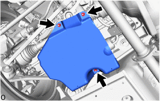
Remove the 3 nuts and No. 2 differential support protector.
-
-
REMOVE NO. 1 DIFFERENTIAL SUPPORT PROTECTOR
Tech Tips
Use the same procedure described for the No. 2 differential support protector.
-
REMOVE REAR SUSPENSION MEMBER BRACE LH
-
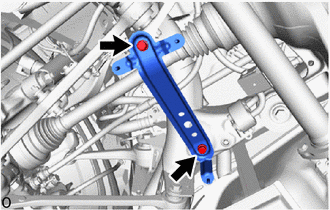
Remove the 2 bolts and rear suspension member brace LH.
-
-
REMOVE REAR SUSPENSION MEMBER BRACE RH
Tech Tips
Use the same procedure as for the LH side.
-
REMOVE REAR AXLE ASSEMBLY LH
-
REMOVE REAR AXLE ASSEMBLY RH
Tech Tips
Use the same procedure as for the LH side.
-
REMOVE REAR DRIVE SHAFT ASSEMBLY LH
-
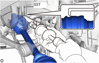
Using SST, remove the rear drive shaft assembly LH.
- SST
- 09520-01010
- 09520-24010 ( 09520-32040 )
Note
-
Do not damage the oil seal, boot and dust cover.
-
Do not drop the rear drive shaft assembly LH.
-
When carrying the rear drive shaft assembly LH, hold it horizontally.
Tech Tips
Hook the SST claw at the position shown in the illustration to remove the rear drive shaft assembly LH.
-
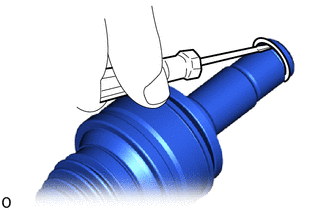
Using a screwdriver, remove the shaft snap ring.
Note
Do not damage the spline of the rear drive shaft assembly LH.
-
-
REMOVE REAR DRIVE SHAFT ASSEMBLY RH
Tech Tips
Use the same procedure as for the LH side.