OIL PUMP MOTOR CONTROLLER INSTALLATION
CAUTION / NOTICE / HINT
CAUTION:
Do not turn the power switch on (READY) until the oil pump motor controller installation is completed.
PROCEDURE
-
INSTALL OIL PUMP MOTOR CONTROLLER
Note
If the oil pump motor controller has been struck or dropped, replace it.
-
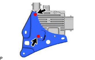
Install the oil pump motor controller bracket to the oil pump motor controller with the 2 bolts.
- Torque:
- 6.0 N*m { 61 kgf*cm, 53 in.*lbf }
-
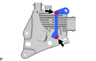
Install the oil pump motor controller bracket to the oil pump motor controller with the 2 bolts.
- Torque:
- 6.0 N*m { 61 kgf*cm, 53 in.*lbf }
-
for LHD:
Install the clamp to the oil pump motor controller bracket.
-
Install the oil pump motor controller with bracket with the 2 nuts.
- Torque:
- 8.5 N*m { 87 kgf*cm, 75 in.*lbf }
-
-
CONNECT CONNECTOR
-
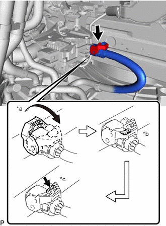
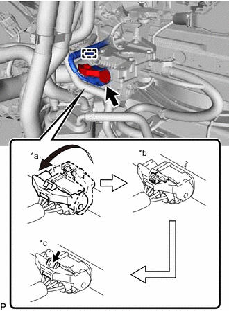
*a Raise the lock lever *b Securely lock the claw *c Push in the lock Connect the connector and securely lock the lock lever as shown in the illustration.
Note
-
Be sure to securely lock the claw of the connector.
-
Push the connector all the way in and lock the lock lever.
Tech Tips
When the connector is pushed all the way in, the lock lever will move slightly towards the lock position.
-
-
Push the lock into the lock lever to securely lock the lock lever of the connector.
Note
Securely lock the lock lever of the connector.
-
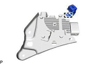
Connect the connector to the oil pump motor controller.
-
*a Raise the lock lever *b Securely lock the claw *c Push in the lock Connect the connector and securely lock the lock lever as shown in the illustration.
Note
-
Be sure to securely lock the claw of the connector.
-
Push the connector all the way in and lock the lock lever.
Tech Tips
When the connector is pushed all the way in, the lock lever will move slightly towards the lock position.
-
-
Push the lock into the lock lever to securely lock the lock lever of the connector.
Note
Securely lock the lock lever of the connector.
-
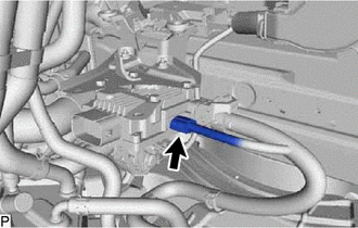
Attach the wire harness clamp to the oil pump motor controller bracket.
-
for LHD:
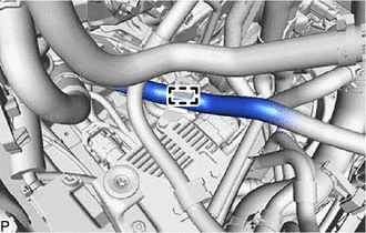
Connect the No. 3 inverter cooling hose to the clamp.
-
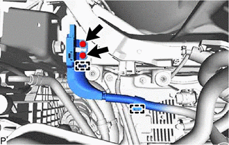
Attach the 2 clamps and connect the ground wire.
-
Install the 2 bolts.
- Torque:
- 10 N*m { 102 kgf*cm, 7 ft.*lbf }
-
-
INSTALL AIR CLEANER ASSEMBLY
-
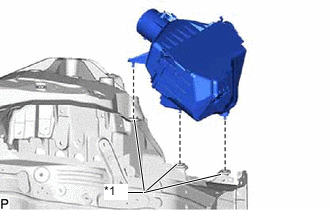
*1 Air Cleaner Support Install the air cleaner assembly to the 3 air cleaner supports.
-
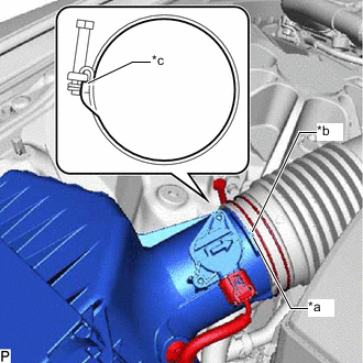
*a Protrusion *b Cutout *c Stopper Align the protrusion of the air cleaner assembly with the cutout of the air cleaner hose assembly, and connect the air cleaner hose assembly to the air cleaner assembly.
-
Tighten while pressing the hose clamp against the stopper on the air cleaner hose assembly.
- Torque:
- 4.0 N*m { 41 kgf*cm, 35 in.*lbf }
-
Connect the intake mass air flow meter connector.
-
Attach the wire harness clamp.
-
-
INSTALL NO. 1 AIR CLEANER INLET
-
INSTALL RADIATOR SUPPORT TO CROSS MEMBER BRACE SUB-ASSEMBLY RH
-
INSTALL RADIATOR LOWER AIR DEFLECTOR
-
INSTALL RADIATOR SUPPORT TO FRAME SEAL RH
-
CONNECT CABLE TO NEGATIVE AUXILIARY BATTERY TERMINAL