ELECTRONIC SHIFT LEVER SYSTEM "Shift system unavailable Apply parking brake securely when parking See owner's manual" is Displayed on Multi-information Display
CAUTION / NOTICE / HINT
Note
-
After turning the power switch off, waiting time may be required before disconnecting the cable from the negative (-) auxiliary battery terminal. Therefore, make sure to read the disconnecting the cable from the negative (-) auxiliary battery terminal notices before proceeding with work.
-
The vehicle is equipped with a sub-battery. Therefore, ensure there is no power being supplied to the vehicle when disconnecting or reconnecting the connector of the shift control ECU and when removing or installing the shift control ECU.
-
Inspect the fuses for circuits related to this system before performing the following inspection procedure.
PROCEDURE
-
CHECK DTC OUTPUT (HYBRID CONTROL)
-
Connect the GTS to the DLC3.
-
Turn the power switch on (IG).
-
With the brake pedal depressed, move the shift lever to select neutral (N).
-
Push the P position switch (shift position indicator) to select park (P).
-
Enter the following menus: Powertrain / Hybrid Control / Trouble Codes.
Powertrain > Hybrid Control > Trouble Codes -
Check if DTCs are output.
Result Result Proceed to None of the DTCs are output. A Any of the DTCs are output. B -
Turn the power switch off.
B 
GO TO DTC CHART Click here
A 
-
-
READ VALUE USING GTS (BATT VOLTAGE FOR GEAR SHIFT CONTROL MODULE)
-
Connect the GTS to the DLC3.
-
Turn the power switch on (IG).
-
Enter the following menus: Powertrain / Hybrid Control / Data List / BATT Voltage for Gear Shift Control Module
-
According to the display on the GTS, read the Data List.
Powertrain > Hybrid Control > Data ListTester Display BATT Voltage for Gear Shift Control Module Result Result Proceed to BATT Voltage for Gear Shift Control Module is 9 V or higher. A BATT Voltage for Gear Shift Control Module is below 9 V. B -
Turn the power switch off.
B 
CHECK AUXILIARY BATTERY VOLTAGE Click here
A
-
-
READ VALUE USING GTS (SUB BATTERY MODULE VOLTAGE)
-
Connect the GTS to the DLC3.
-
Turn the power switch on (IG).
-
Enter the following menus: Body Electrical / Sub Battery Module / Active Test / Protection Relay
-
According to the display on the GTS, read the Data List.
Body Electrical > Sub Battery Module > Active TestActive Test Display Protection Relay Data List Display Sub Battery Module Voltage -
Using the Dual Data List function in the GTS, read the Data List item "Sub Battery Module Voltage" during the Active Test (protection relay ON).
Result Result Proceed to The "Sub Battery Module Voltage" is 9 V or higher while the Active Test is being performed (protection relay ON) A The "Sub Battery Module Voltage" is below 9 V while the Active Test is being performed (protection relay ON) B -
Turn the power switch off.
B
CHECK SUB-BATTERY MODULE ASSEMBLY VOLTAGE Click here
A
-
-
CHECK DIAGNOSIS RELATED INFORMATION (HYBRID CONTROL)
-
Connect the GTS to the DLC3.
-
Turn the power switch on (IG).
-
Enter the following menus: Powertrain / Hybrid Control / Utility / Diagnosis Related Information.
Powertrain > Hybrid Control > UtilityTester Display Diagnosis Related Information -
Check for diagnosis related information.
Result Result Proceed to No diagnosis related information is output. A The diagnosis related information in the table below is output. B Diagnosis Related Information P085011 P085015 -
Turn the power switch off.
B
CHECK CONNECTOR CONNECTION CONDITION (SHIFT CONTROL ECU CONNECTOR) Click here
A
-
-
INSPECT P CON MTR RELAY
-
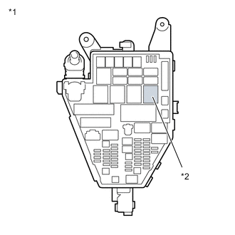
*1 No. 1 Engine Room Relay Block and Junction Block Assembly *2 P CON MTR Relay Remove the P CON MTR relay from the No. 1 engine room relay block and junction block assembly.
-
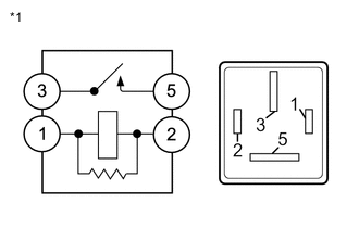
*1 P CON MTR Relay Measure the resistance according to the value(s) in the table below.
Standard Resistance Tester Connection Condition Specified Condition 3 - 5 Auxiliary battery voltage not applied between terminals 1 and 2 10 kΩ or higher Auxiliary battery voltage applied between terminals 1 and 2 Below 1 Ω -
Install the P CON MTR relay.
Result Proceed to OK NG
NG
REPLACE P CON MTR RELAY
OK
-
-
INSPECT P CON MTR2 RELAY
-
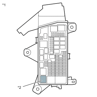
*1 No. 2 Luggage Room Relay Block Assembly *2 P CON MTR2 Relay Remove the P CON MTR2 relay from the No. 2 luggage room relay block assembly.
-
*1 P CON MTR2 Relay Measure the resistance according to the value(s) in the table below.
Standard Resistance Tester Connection Condition Specified Condition 3 - 5 Auxiliary battery voltage not applied between terminals 1 and 2 10 kΩ or higher Auxiliary battery voltage applied between terminals 1 and 2 Below 1 Ω -
Install the P CON MTR2 relay.
Result Proceed to OK NG
OK
REPLACE SHIFT CONTROL ECU Click here
NG
REPLACE P CON MTR2 RELAY
-
-
CHECK CONNECTOR CONNECTION CONDITION (SHIFT CONTROL ECU CONNECTOR)
-
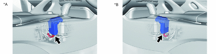
Check the connector connections and contact pressure of the relevant terminals for the shift control ECU connectors.
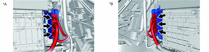
*A for RHD *B for LHD OK The connectors are connected securely and there are no contact pressure problems. Result Proceed to OK NG
NG
CONNECT SECURELY
OK
-
-
CHECK CONNECTOR CONNECTION CONDITION (P POSITION SWITCH (SHIFT POSITION INDICATOR) CONNECTOR)
-
Check the connector connections and contact pressure of the relevant terminals for the P position switch (shift position indicator) connector.
*A for RHD *B for LHD OK The connector is connected securely and there are no contact pressure problems. Result Proceed to OK NG
NG
CONNECT SECURELY
OK
-
-
CHECK HARNESS AND CONNECTOR (SHIFT CONTROL ECU - P POSITION SWITCH (SHIFT POSITION INDICATOR))
-
Disconnect the P75 shift control ECU connector.
-
Disconnect the P39 P position switch (shift position indicator) connector.
-
Measure the resistance according to the value(s) in the table below.
Standard Resistance (Check for Open) Tester Connection Condition Specified Condition P75-10 (P1) - P39-14 (S) Always Below 1 Ω Standard Resistance (Check for Short) Tester Connection Condition Specified Condition P75-10 (P1) or P39-14 (S) - Body ground and other terminals Always 10 kΩ or higher -
Reconnect the P39 P position switch (shift position indicator) connector.
-
Reconnect the P75 shift control ECU connector.
Result Proceed to OK NG
OK
CHECK FOR INTERMITTENT PROBLEMS Click here
NG
REPAIR OR REPLACE HARNESS OR CONNECTOR
-
-
CHECK SUB-BATTERY MODULE ASSEMBLY VOLTAGE
-
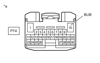
*a Front view of wire harness connector
(to Shift Control ECU)
Disconnect the shift control ECU connector.
-
Turn the power switch on (IG)
-
Measure the voltage according to the value(s) in the table below.
Standard Voltage Tester Connection Condition Specified Condition P74-10 (BUB) - Body ground 5 seconds after turning the power switch on (IG) 8 to 15.4 V Note
-
Power is supplied from the sub-battery module assembly for only 5 seconds after the power switch is turned on (IG). Therefore, measure the voltage during that time.
-
Turning the power switch on (IG) with the connector disconnected causes other DTCs to be stored. Clear the DTCs after performing this inspection.
-
-
Turn the power switch off
-
Reconnect the shift control ECU connector.
Result Proceed to OK NG
OK
REPLACE SHIFT CONTROL ECU Click here
NG
-
-
CHECK HARNESS AND CONNECTOR (SHIFT CONTROL ECU - P CON MAIN2 FUSE)
-
Disconnect the shift control ECU connector.
-
Remove the P CON MAIN2 fuse from the No. 1 luggage room relay block assembly.
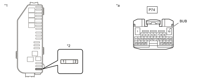
*1 No. 1 Luggage Room Relay Block Assembly *2 P CON MAIN2 FUSE *a Front view of wire harness connector
(to Shift Control ECU)
- - -
Measure the resistance according to the value(s) in the table below.
Standard Resistance (Check for Open) Tester Connection Condition Specified Condition P CON MAIN2 fuse terminal 2 - P74-10 (BUB) Always Below 1 Ω Standard Resistance (Check for Short) Tester Connection Condition Specified Condition P CON MAIN2 fuse terminal 2 or P74-10 (BUB) - Body ground Always 10 kΩ or higher -
Reconnect the shift control ECU connector.
-
Install the P CON MAIN2 fuse.
Result Proceed to OK NG
NG
REPAIR OR REPLACE HARNESS OR CONNECTOR
OK
-
-
CHECK HARNESS AND CONNECTOR (P CON MAIN2 FUSE - SUB-BATTERY MODULE ASSEMBLY)
-
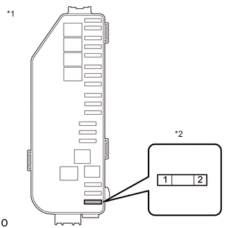
*1 No. 1 Luggage Room Relay Block Assembly *2 P CON MAIN2 Fuse Remove the P CON MAIN2 fuse from the No. 1 luggage room relay block assembly.
-
Disconnect the b7 positive (+) terminal from the sub-battery module assembly.
-
Measure the resistance according to the value(s) in the table below.
Standard Resistance (Check for Open) Tester Connection Condition Specified Condition P CON MAIN2 fuse terminal 1 - b7-1(+BAT) Always Below 1 Ω Standard Resistance (Check for Short) Tester Connection Condition Specified Condition P CON MAIN2 fuse terminal 1 or b7-1(+BAT) - Body ground Always 10 kΩ or higher -
Install the P CON MAIN2 fuse.
-
Reconnect the b7 positive (+) terminal to the sub-battery module assembly.
Result Proceed to OK NG
OK
CHECK SUB BATTERY SYSTEM Click here
NG
REPAIR OR REPLACE HARNESS OR CONNECTOR
-
-
CHECK AUXILIARY BATTERY VOLTAGE
-
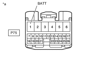
*a Front view of wire harness connector
(to Shift Control ECU)
Disconnect the shift control ECU connector.
-
Measure the voltage according to the value(s) in the table below.
Standard Voltage Tester Connection Switch Condition Specified Condition P75-1 (BATT) - Body ground Power switch off 8 to 15.4 V -
Reconnect the shift control ECU connector.
Result Proceed to OK NG
OK
REPLACE SHIFT CONTROL ECU Click here
NG
-
-
CHECK HARNESS AND CONNECTOR (SHIFT CONTROL ECU - P CON MAIN FUSE)
-
Disconnect the shift control ECU connector.
-
Remove the P CON MAIN fuse from the No. 1 engine room relay block and junction block assembly.
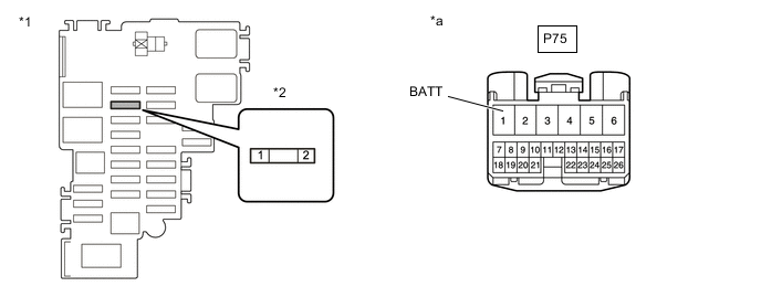
*1 No. 1 Engine Room Relay Block and Junction Block Assembly *2 P CON MAIN FUSE *a Front view of wire harness connector
(to Shift Control ECU)
- - -
Measure the resistance according to the value(s) in the table below.
Standard Resistance (Check for Open) Tester Connection Condition Specified Condition P CON MAIN fuse terminal 2 - P75-1 (BATT) Always Below 1 Ω Standard Resistance (Check for Short) Tester Connection Condition Specified Condition P CON MAIN fuse terminal 2 or P75-1 (BATT) - Body ground Always 10 kΩ or higher -
Reconnect the shift control ECU connector.
-
Install the P CON MAIN fuse.
Result Proceed to OK NG
NG
REPAIR OR REPLACE HARNESS OR CONNECTOR
OK
-
-
CHECK HARNESS AND CONNECTOR (P CON MAIN FUSE - AUXILIARY BATTERY)
-
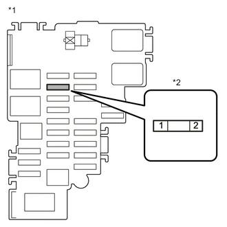
*1 No. 1 Engine Room Relay Block and Junction Block Assembly *2 P CON MAIN Fuse Remove the P CON MAIN fuse from the No. 1 engine room relay block and junction block assembly.
-
Disconnect the cable from the negative (-) auxiliary battery terminal.
-
Disconnect the cable from the positive (+) auxiliary battery terminal.
-
Measure the resistance according to the value(s) in the table below.
Standard Resistance (Check for Open) Tester Connection Condition Specified Condition P CON MAIN fuse terminal 1 - Auxiliary battery positive (+) cable Always Below 1 Ω Standard Resistance (Check for Short) Tester Connection Condition Specified Condition P CON MAIN fuse terminal 1 - Body ground Always 10 kΩ or higher -
Connect the cable to the positive (+) auxiliary battery terminal.
-
Connect the cable to the negative (-) auxiliary battery terminal.
-
Install the P CON MAIN fuse.
Result Proceed to OK NG
NG
REPAIR OR REPLACE HARNESS OR CONNECTOR
OK
-
-
CHARGE AUXILIARY BATTERY
-
Charge the auxiliary battery.
Result Proceed to NEXT
NEXT
-
-
CHECK OPERATION
-
Turn the power switch on (IG).
-
Depress the brake pedal and move the shift lever to select neutral (N).
-
Push the P position switch (shift position indicator) to select park (P).
-
Check that if there is a error message displayed on the multi-information display.
Result Result Proceed to "Shift system unavailable Apply parking brake securely when parking See owner's manual" is not displayed on the multi-information display. A "Shift system unavailable Apply parking brake securely when parking See owner's manual" is displayed on the multi-information display. B -
Turn the power switch off.
A
END
B
REPLACE AUXILIARY BATTERY Click here
-