ELECTRONIC SHIFT LEVER SYSTEM P Position Switch Indicator Circuit
DESCRIPTION
The P position switch (shift position indicator) ON (indicator illuminates (shift state park (P))) or OFF (indicator goes off (shift state other than park (P))) is displayed.
The P position switch indicator goes off when a system malfunction occurs (not in all cases) and a warning message will also be displayed on the multi-information display.
WIRING DIAGRAM
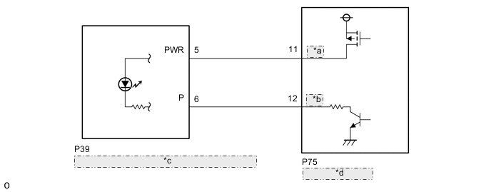
| *a | ACCI |
| *b | INDP |
| *c | P Position Switch (Shift Position Indicator) |
| *d | Shift Control ECU |
CAUTION / NOTICE / HINT
Note
The vehicle is equipped with a sub-battery. Therefore, ensure there is no power being supplied to the vehicle when disconnecting or reconnecting the connector of the shift control ECU and when removing or installing the shift control ECU.
PROCEDURE
-
CHECK P POSITION SWITCH (SHIFT POSITION INDICATOR) (INDICATOR STATUS)
-
Turn the power switch on (IG).
-
Depress the brake pedal and move the shift lever to select neutral (N).
-
Operate the P position switch (shift position indicator) and check the condition of the indicator.
Result Condition of Indicator Proceed to Indicator does not go off. (Remains on) A Indicator does not come on. B -
Turn the power switch off.
B 
CHECK HARNESS AND CONNECTOR (P POSITION SWITCH (SHIFT POSITION INDICATOR) POWER SOURCE CIRCUIT) Click here
A 
-
-
CHECK P POSITION SWITCH (SHIFT POSITION INDICATOR) (CHECK ILLUMINATION)
-
Disconnect the P75 shift control ECU connector.
-
Turn the power switch on (IG).
-
Inspect the P position switch indicator condition.
Result Result Proceed to Indicator illuminates A Indicator goes off. B Note
Turning the power switch on (IG) with the shift control ECU connector disconnected causes other DTCs to be stored. Clear the DTCs after performing this inspection.
-
Turn the power switch off.
-
Reconnect the P75 shift control ECU connector.
B 
REPLACE SHIFT CONTROL ECU Click here
A
-
-
CHECK HARNESS AND CONNECTOR (SHIFT CONTROL ECU - P POSITION SWITCH (SHIFT POSITION INDICATOR))
-
Disconnect the P75 shift control ECU connector.
-
Disconnect the P39 P position switch (shift position indicator) connector.
-
Measure the resistance according to the value(s) in the table below.
Standard Resistance (Check for Short) Tester Connection Condition Specified Condition P75-12(INDP) or P39-6(P) - Body ground and other terminals Always 10 kΩ or higher -
Reconnect the P39 P position switch (shift position indicator) connector.
-
Reconnect the P75 shift control ECU connector.
Result Proceed to OK NG
OK
REPLACE SHIFT POSITION INDICATOR Click here
NG
REPAIR OR REPLACE HARNESS OR CONNECTOR
-
-
CHECK HARNESS AND CONNECTOR (P POSITION SWITCH (SHIFT POSITION INDICATOR) POWER SOURCE CIRCUIT)
-
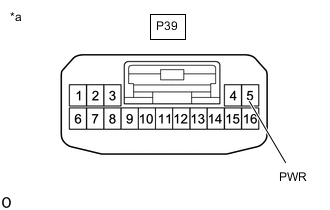
*a Front view of wire harness connector
(to P Position Switch (Shift Position Indicator))
Disconnect the P position switch (shift position indicator) connector.
-
Turn the power switch on (IG).
-
Measure the voltage according to the value(s) in the table below.
Standard Voltage Tester Connection Switch Condition Specified Condition P39-5(PWR) - Body ground Power switch on (IG) 9 to 14 V Note
Turning the power switch on (IG) with the connector disconnected causes other DTCs to be stored. Clear the DTCs after performing this inspection.
-
Turn the power switch off.
-
Reconnect the P position switch (shift position indicator) connector.
Result Proceed to OK NG
NG
CHECK HARNESS AND CONNECTOR (SHIFT CONTROL ECU - P POSITION SWITCH (SHIFT POSITION INDICATOR)) Click here
OK
-
-
INSPECT P POSITION SWITCH (SHIFT POSITION INDICATOR)
-
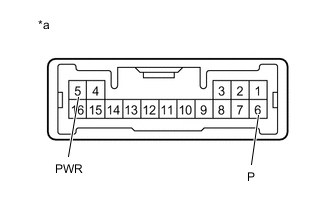
*a Component without harness connected
(P Position Switch (Shift Position Indicator))
Disconnect the P position switch (shift position indicator) connector.
-
Apply auxiliary battery voltage between terminals 5(PWR) and 6(P) and check the indicator.
Result Condition Specified Condition Auxiliary battery voltage applied between terminals 5(PWR) and 6(P) Comes on -
Reconnect the P position switch (shift position indicator) connector.
Result Proceed to OK NG
NG
REPLACE P POSITION SWITCH (SHIFT POSITION INDICATOR) Click here
OK
-
-
CHECK HARNESS AND CONNECTOR (SHIFT CONTROL ECU - P POSITION SWITCH (SHIFT POSITION INDICATOR))
-
Disconnect the P75 shift control ECU connector.
-
Disconnect the P39 P position switch (shift position indicator) connector.
-
Measure the resistance according to the value(s) in the table below.
Standard Resistance (Check for Open) Tester Connection Condition Specified Condition P75-12 (INDP) - P39-6 (P) Always Below 1 Ω -
Reconnect the P39 P position switch (shift position indicator) connector.
-
Reconnect the P75 shift control ECU connector.
Result Proceed to OK NG
OK
REPLACE SHIFT CONTROL ECU Click here
NG
REPAIR OR REPLACE HARNESS OR CONNECTOR
-
-
CHECK HARNESS AND CONNECTOR (SHIFT CONTROL ECU - P POSITION SWITCH (SHIFT POSITION INDICATOR))
-
Disconnect the P75 shift control ECU connector.
-
Disconnect the P39 P position switch (shift position indicator) connector.
-
Measure the resistance according to the value(s) in the table below.
Standard Resistance (Check for Open) Tester Connection Condition Specified Condition P75-11 (ACCI) - P39-5 (PWR) Always Below 1 Ω Standard Resistance (Check for Short) Tester Connection Condition Specified Condition P75-11 (ACCI) or P39-5 (PWR) - Body ground and other terminals Always 10 kΩ or higher -
Reconnect the P39 P position switch (shift position indicator) connector.
-
Reconnect the P75 shift control ECU connector.
Result Proceed to OK NG
OK
REPLACE SHIFT CONTROL ECU Click here
NG
REPAIR OR REPLACE HARNESS OR CONNECTOR
-