ELECTRONIC SHIFT LEVER SYSTEM, Diagnostic DTC:P085011, P085015
| DTC Code | DTC Name |
|---|---|
| P085011 | Park/Neutral Switch Circuit Short to Ground |
| P085015 | Park/Neutral Switch Circuit Short to Auxiliary Battery or Open |
DESCRIPTION
Instead of having a parking position as one of the positions as on a conventional shift lever, a P position switch (shift position indicator) is provided independently under the shift lever. The switch is a momentary type, in which the button does not lock mechanically.
The P position switch (shift position indicator) contains resistors R1, R2, R3 and R4. When the P position switch (shift position indicator) is not pressed, the switch provides a combined resistance of R3 and R4; and when the P position switch (shift position indicator) is pressed, the switch provides a combined resistance of R1, R2, R3 and R4. The voltage at the P1 terminal of the shift control ECU varies with the changes in the resistance of the switch. The shift control ECU determines the P position switch (shift position indicator) operation according to this resistance signal.
| DTC No. | Detection Item | DTC Detection Condition | Trouble Area | Warning Indicate |
|---|---|---|---|---|
| P085011 | Park/Neutral Switch Circuit Short to Ground | 1. 0.5 seconds or more elapse after turning power switch on (READY) with battery voltage 10 V or higher, P1 terminal voltage of P position switch circuit is continuously lower than specified value for 2 seconds or more (1 trip detection logic) |
|
|
| P085015 | Park/Neutral Switch Circuit Short to Auxiliary Battery or Open | 1. 0.5 seconds or more elapse after turning power switch on (READY) with battery voltage 10 V or higher, P1 terminal voltage of P position switch circuit is continuously higher than specified value for 2 seconds or more (1 trip detection logic) |
|
|
| DTC No. | Data List |
|---|---|
| P085011 |
|
| P085015 |
*1: While the P position switch (shift position indicator) is being pushed, the value for Data List item "P Position Switch Terminal Voltage (Gear Shift Control Module)" will decrease.
CONFIRMATION DRIVING PATTERN
Tech Tips
After repair has been completed, clear the DTC and then check that the vehicle has returned to normal by performing the All Readiness check procedure.
-
Turn the power switch on (READY).
-
Depress the brake pedal and move the shift lever to select neutral (N).
-
Push the P position switch (shift position indicator) to select park (P).
WIRING DIAGRAM
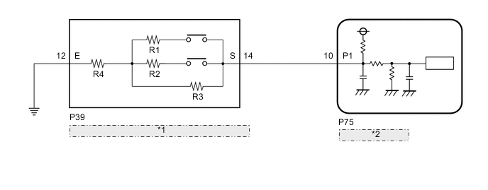
| *1 | P Position Switch (Shift Position Indicator) |
| *2 | Shift Control ECU |
CAUTION / NOTICE / HINT
Note
The vehicle is equipped with a sub-battery. Therefore, ensure there is no power being supplied to the vehicle when disconnecting or reconnecting the connector of the shift control ECU and when removing or installing the shift control ECU.
PROCEDURE
-
INSPECT P POSITION SWITCH (SHIFT POSITION INDICATOR)
-
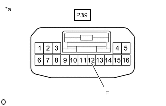
*a Component without harness connected
(P Position Switch (Shift Position Indicator))
Disconnect the P position switch (shift position indicator) connector.
-
Measure the resistance according to the value(s) in the table below.
Standard Resistance Tester Connection Switch Condition Specified Condition 14 (S) - 12 (E) Switch being pressed 613 to 751 Ω 14 (S) - 12 (E) Switch released 3.9 to 4.9 kΩ -
Reconnect the P position switch (shift position indicator) connector.
Result Proceed to OK NG
NG 
REPLACE P POSITION SWITCH (SHIFT POSITION INDICATOR)
OK 
-
-
CHECK HARNESS AND CONNECTOR (SHIFT CONTROL ECU - P POSITION SWITCH (SHIFT POSITION INDICATOR))
-
Disconnect the P75 shift control ECU connector.
-
Disconnect the P39 P position switch (shift position indicator) connector.
-
Measure the resistance according to the value(s) in the table below.
Standard Resistance (Check for Open) Tester Connection Condition Specified Condition P75-10 (P1) - P39-14 (S) Always Below 1 Ω Standard Resistance (Check for Short) Tester Connection Condition Specified Condition P75-10 (P1) or P39-14 (S) - Body ground and other terminals Always 10 kΩ or higher -
Reconnect the P39 P position switch (shift position indicator) connector.
-
Reconnect the P75 shift control ECU connector.
Result Proceed to OK NG
NG
REPAIR OR REPLACE HARNESS OR CONNECTOR
OK
-
-
CHECK HARNESS AND CONNECTOR (P POSITION SWITCH (SHIFT POSITION INDICATOR) - BODY GROUND)
-
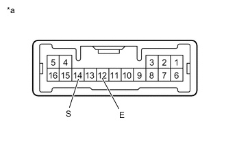
*a Front view of wire harness connector
(to P Position Switch (Shift Position Indicator))
Disconnect the P position switch (shift position indicator) connector.
-
Measure the resistance according to the value(s) in the table below.
Standard Resistance (Check for Open) Tester Connection Condition Specified Condition P39-12 (E) - Body ground Always Below 1 Ω -
Reconnect the P position switch (shift position indicator) connector.
Result Proceed to OK NG
OK
REPLACE SHIFT CONTROL ECU Click here
NG
REPAIR OR REPLACE HARNESS OR CONNECTOR
-