OIL PUMP MOTOR CONTROLLER REMOVAL
CAUTION / NOTICE / HINT
CAUTION:
Do not turn the power switch on (READY) until the oil pump motor controller installation is completed.
The necessary procedures (adjustment, calibration, initialization or registration) that must be performed after parts are removed and installed, or replaced during oil pump motor controller removal/installation are shown below.
Note
After turning the power switch off, waiting time may be required before disconnecting the cable from the negative (-) auxiliary battery terminal. Therefore, make sure to read the disconnecting the cable from the negative (-) auxiliary battery terminal notices before proceeding with work.
| Replaced Part or Performed Procedure | Necessary Procedure | Effect/Inoperative Function when Necessary Procedure not Performed | Link |
|---|---|---|---|
| Auxiliary battery terminal is disconnected/reconnected | Memorize steering angle neutral point | LKA/LDA system | |
| Pre-collision system | |||
| Parking assist monitor system | |||
| Steering sensor zero point calibration | Variable gear ratio steering system |
Note
After the power switch is turned off, the navigation system requires approximately a minute to record various types of memory and settings. As a result, after turning the power switch off, wait a minute or more before disconnecting the cable from the negative (-) auxiliary battery terminal.
PROCEDURE
-
DISCONNECT CABLE FROM NEGATIVE AUXILIARY BATTERY TERMINAL
-
REMOVE RADIATOR SUPPORT TO FRAME SEAL RH
-
REMOVE RADIATOR LOWER AIR DEFLECTOR
-
REMOVE RADIATOR SUPPORT TO CROSS MEMBER BRACE SUB-ASSEMBLY RH
-
REMOVE NO. 1 AIR CLEANER INLET
-
REMOVE AIR CLEANER ASSEMBLY
-
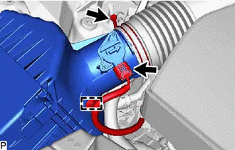
Detach the wire harness clamp.
-
Disconnect the intake mass air flow meter connector.
-
Loosen the hose clamp and disconnect the air cleaner hose assembly from the air cleaner assembly.
-
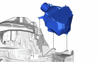
*1 Air Cleaner Support Remove the air cleaner assembly from the 3 air cleaner supports.
-
-
DISCONNECT CONNECTOR
-
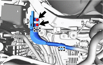
Remove the 2 bolts.
-
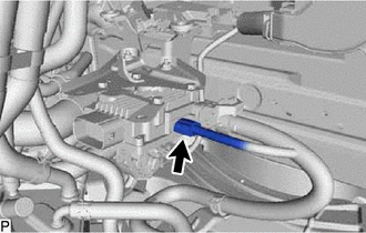
Detach the 2 clamps and disconnect the ground wire.
-
for LHD:
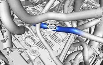
Disconnect the No. 3 inverter cooling hose.
-
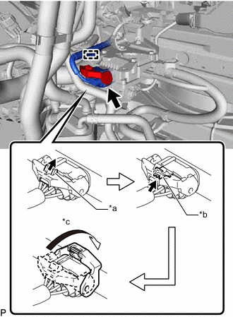
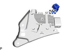
*a Pull out the lock *b Release the lock *c Rotate the lock lever Detach the wire harness clamp from the oil pump motor controller bracket.
-
Pull out the lock of the connector.
-
Release the lock of the connector.
-
Release the lock lever of the connector as shown in the illustration. Disconnect the connector from the oil pump motor controller.
-
Disconnect the connector from the oil pump motor controller.
-
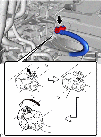
*a Pull out the lock *b Release the lock *c Rotate the lock lever Pull out the lock of the connector.
-
Release the lock of the connector.
-
Release the lock lever of the connector as shown in the illustration. Disconnect the connector from the oil pump motor controller.
-
-
REMOVE OIL PUMP MOTOR CONTROLLER
Note
If the oil pump motor controller has been struck or dropped, replace it.
-
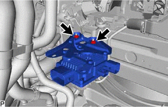
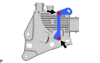
Remove the 2 nuts and oil pump motor controller with bracket.
-
for LHD:
Remove the clamp from the oil pump motor controller bracket.
-
Remove the 2 bolts and oil pump motor controller bracket from the oil pump motor controller.
-
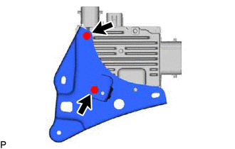
Remove the 2 bolts and oil pump motor controller bracket from the oil pump motor controller.
-